WHEN Cm<t > 0 (AERODYNAMICALLY UNSTABLE CONFIGURATION)
In this case c4 and c0 are positive definite whereas c2 changes sign from negative to positive as p0 increases. The only possibility for stable roots is A2 < 0, in which case A is imaginary, corresponding to gyroscopic motion. If A2 is real and positive, or complex, there will be at least one root with a positive real part. Thus the conditions to be met are A2 real and <0, for which it is necessary and sufficient that c22 > 4c0c4. The roll rate required for stability is then given by
![]() л 2
л 2
Pо >—ГГ
rr.
WHEN Cma < 0 (AERODYNAMICALLY STABLE CONFIGURATION)
In this case c2 and c4 are positive definite and it is c0 that can change sign. The condition (10.7,6) still holds, but because Gm is now negative, it is automatically satisfied. However, the condition that A2 be negative now requires that c0 be positive. So for this case the criterion for p0 is obtained from c0 > 0, i. e.
Condition (10.7,7) is met for all values of p02 except one, at which the l. h.s. = 0. There is thus one roll rate at which the system has “neutral” stability, i. e. for which there is a zero root. The critical value is
To summarize, we have seen that an aerodynamically unstable configuration can be stabilized by spinning it fast enough, and that at a certain critical roll rate an aerodynamically stable configuration becomes neutrally stable. The source of these phenomena is the inertia effects given by the rp and qp terms in the pitching and yawing moment equations. They can be thought of as gyroscopic moments associated with high roll rate. Phillips (ref. 10.1) has analyzed a more general case, in which the vehicle is not axisymmetric, and in which aerodynamic forces as well as moments are retained, i. e. an airplane configuration. In this case he found that there is a band of roll rates within which the vehicle is unstable, the lower critical one being given approximately by the lesser of
![]() (10.7,9)
(10.7,9)
[compare with (10.7,8)].
For the jet transport of our examples, with Cm = —.488 the critical rate would be pcrit = .112, corresponding to the first of the two criteria. From
(10.6,8) this vehicle, at da = 20°, achieves pss = .0528, a value considerably less than the critical, and hence one would not anticipate any difficulties for this airplane arising from nonlinear inertia coupling.
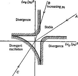
Since the rolling motion may be thought of in a sense as providing a periodic excitation of the uncoupled longitudinal and lateral oscillations, it proves convenient to look at stability boundaries in the plane of the two uncoupled frequencies. This idea was first used by Phillips. The result is typically like that in Fig. 10.17, the exact boundaries depending mainly on the dampings of the two oscillations. A vehicle conventionally stable in nonrolling flight would be represented by a point in the upper right quadrant, the exact position being determined by pn. As p0 increases, the point moves radially toward the origin. If it follows a line like A, there will be no instability; but if like B, there is an unstable range of p0 separating two stable regions as found by Phillips. A vehicle that is statically unstable in both pitch and yaw when nonrolling will correspond to a point in the lower left quadrant, and can be stabilized by a large enough p0 (line C).
|
Fig. 10.17 Form of stability boundaries for rolling vehicle. cov = frequency of yaw oscillation, V/NpJIz. o>g = frequency of pitch oscillation, V —Mxfly. |


