Behavior of a Wing in a Propeller Slipstream
Several approaches to the problem of a wing in a propeller slipstream can be found in the literature. None of these is quite satisfactory. Either the physical model is too simplified and restricted in its range of application or more exact solutions are too complicated for practical application.
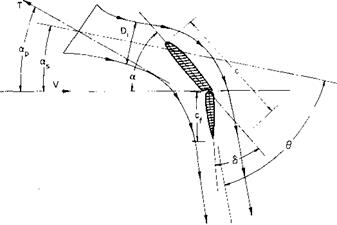
In general, a solution applicable over an extreme range of operating conditions, including wing angle of attack, flap angle, and propeller loading, is required. Consider the arbitrary wing-propeller combination shown in Figs. 8-9 and 8-10.
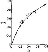
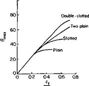
In this figure Di is the contracted slipstream diameter, c is the wing chord in the slipstream, and cf is the flap chord; 0 is the angle through which the slipstream is turned by the wing. Reference 2 argues on the basis of experimental data that the ratio of this angle to d is a function primarily of the ratio of cf to Dv Figure 8-11 taken from the reference presents this relationship together with the limitation of в. The maximum 0 depends both on the type of flap and the ratio cf! Dl.
Consider the limiting case in which Dj becomes small as the number of propellers N becomes large. The wing is then submerged in a thin jet which
|
Fig. 8-9. Propeller-wing combination: a. p = prop angle of attack; as = slipstream angle of attack; a = wing angle of attack; S = flap angle; (I = angle through which slipstream is turned. |
follows the contour of the airfoil and leaves tangent to the trailing edge. This is seen to be analogous to a jet-flap. The momentum coefficient Сц for the equivalent jet-flap would be approximately
![]()
 |
NT
w
where N is the number of propellers, T is the thrust of each propeller, q is the free-stream dynamic pressure, and S is the projected wing area immersed in the stream. When Dt increases, it is assumed that the analogy to the jet flap will still hold if the angle at which the jet leaves the airfoil is obtained from Fig. 8-11.
 |
 |
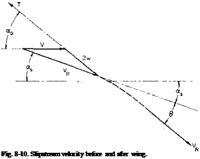
From Fig. 8-10 VR sin as = 2w sin ap. The vertical component of the
Fig. 8-11. Turning performance of flaps.
thrust is T sin ap = mVR sin as, where m is the mass flow rate through the propeller. The vertical component of the deflected thrust is mVR sin (as + 0). Hence the vertical lift of the turned slipstream in dimensionless form is
Ct(prop) = C„ sin (as + 0).
Thus the lift of the wing-propeller combination can be expressed as the sum of three parts:
CLt=о is the lift that the wing would produce without the propellers. The last term is the vertical component that results from the turning of the momentum in the slipstream. CLr is the lift that results from the additional circulation produced by the effect of the slipstream acting as a jet flap on the flow external to the slipstream.
In addition, CL must be reduced by the vertical component of the profile drag of the wing immersed in the propeller slipstream. This drag, proportional to VR, must reduce VR by an increment AKR so that
D = jpVRSCD = m &VR
or
AFr D sin as
VR T sin ap
Hence Eq. (8-15) becomes
Cl = Ci-° + + C"sin (“s + 6) (S “ t}
We can estimate CD to obtain D/T or use the fact that for the same turning
D _ yVjCdS T pAV’2w
but
(D _ jP(2w0)2CdS
T )v = o 2pAwl
= C^S A ‘
Therefore
D=(£ Ії_
T Tjy=0 4 V’w
V = [(F + w cos ap)2 + (w sin ap)2]1/2.
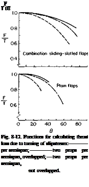
The quantity 1 — (D/TV=0 is defined in Ref. 2 as the thrust recovery factor F/T. Hence CL finally becomes
The function F/T is presented in Fig. 8-12.
There are two other effects that have not been considered. First, the slipstream may increase CLr=o. The accelerating flow in the slipstream may provide some boundary layer control that would delay separation.

і о
Second, at an angle of attack a propeller produces a force normal to its axis. In general, however, in the range of interest these effects, in comparison with the other terms in (8-16), are negligible.
CLv can be calculated from two-dimensional jet flap theory corrected for finite aspect ratio from Fig. 3-17 or Eq. (7-21) and for vortex sheet deflection from Fig. 3-10. Figure 3-8 should also be checked for the limiting CL.
From Spence’s developments [2] C, for the two-dimensional jet flap is given by
C, r = Cta + CJ (8-17)
where
C, a = 1.152л/с~„ + 0.106C,, + 0.051C2/2 per radian,
Cl6 = 3.54- 0.675C„ + 0.156C2/2 per radian.
In these equations the contribution to C, of the jet reaction and angle of attack for C„ = 0 has been removed.
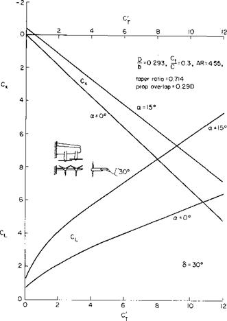
The above is perhaps best explained by means of an example. In Ref. 3 the data of Fig. 8-13 is presented. For illustrative purposes consider a = 15°, 5 = 30°, and C’T — 8; C, is defined according to (8-14), hence Cp — C’T = 8, but C„ and wJV are related by
For this example
![]() Ap 24 n ~S = 4(18.17)
Ap 24 n ~S = 4(18.17)
Therefore
From Fig. 8-3, w/w0 = 0.69 so that 2w/V = 2(0.69/0.72) = 1.92. The velocity diagram of the slipstream going into the wing is thus shown in Fig. 8-14.
First, considering the turning of the slipstream by the wing at an angle of 5.2°, from Fig. 8-11 for c/D = 0.76, 6/a = 0.9 so that в = 4.7. Added to this is the contribution of the flap. For this cf/D = 0.25 so that 0/<5 = 0.5 or в = 15°. The total в is thus 19.7. On the average, therefore, the slipstream leaves at an angle of 9.8 + 19.7, or 29.5° from the horizontal. Hence C, r is given by
Ci r = Ctx + Cl6(<xs + в – a)
or
|
|
|
|
|
|
|
Fig. 8-13. Experimental longitudinal force and lift coefficients for plain flap: C j — NT/qS Cx = FJqS S = wing area. |
|
Fig. 8-14. Example slipstream velocity diagram. |
where
Cu = 1.152^8 + 0.106(8) + 0.051(8)3/2 = 5.16,
Cu = 3.54^8 – 0.675(8) + 0.156(8)3/2 = 8.13,
or
C, r == 1.35 + 2.05 = 3.40.
From Fig. 8-12 F/T =* 1.0, and there is no significant correction to C, for
turning losses.
 |
|
The aspect ratio of the example wing is approximately 4.5. From Fig. 3-17 C, r is reduced to 2.17; CL for T = 0 for this wing is 1.2. The redirected thrust contribution is
Hence the total predicted CL is
CL = 1.2 + 2.17 + 5.92 = 9.29.
By comparison with Fig. 8-13 the predicted CL is seen to be a little higher than the experimental value.
Consider the same case but for a = 0°. w/V is nearly the same so that for this case the slipstream is turned through an angle of only 15°; CL = 0.8 for T = 0 for this case, whereas
Clr=Cu5
= 2.12.
Correcting for AR, CLr = 1.35. Hence
CL = 0.8 + 1.35 + 8 sin (15°)
= 4.22.
This predicted value is somewhat lower than the measured value, but the agreement is certainly satisfactory for preliminary design purposes.


