Biot-Savart Law
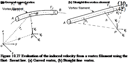
Fundamental to all vortex models is the requirement to compute the induced velocity at a point contributed by a vortex filament in the rotor wake. This can be calculated through the application of the Biot-Savart law – see Batchelor (1967). The incremental values of induced velocity, dv, at any point P a distance r from the segment dl of a vortex
 |
filament of strength Г„ can be written in general form as
which is shown schematically in Fig. 10.27. The total velocity at point P is then obtained by integration along the lengths of the vortex filaments. In application, curved wake filaments would normally be discretized into a number of collocation points that are connected by straight-line vortex segments because the velocity induced by a straight-line vortex segment is then readily integrable. The velocity at a point P induced by a single, straight-line vortex element extending from one point A to another point В [see Fig. 10.27(b)] can be expressed in the form
 |
where![]()
 |
|
Vortex Segmentation
To help reduce the number of numerical operations associated with vortex methods, the complexity of the real rotor wake can be reduced into various simplified forms. A common approximation is to treat only the trailed vortex filaments, that is, the filaments that are initially trailed perpendicular to the blade span (see Fig. 8.3). These contributions to the vorticity field arise because of the spanwise gradients in the distribution of circulation loading on the blades. The time-dependent aerodynamic loading results in shed wake vorticity, and to save tracking all the shed elements in the wake this effect can be approximated by means of one of the unsteady aerodynamic models considered in Chapter 8. Even with the trailed wake system alone, the problem of calculating the induced velocity field is still one of high numerical cost. However, experiments have shown the dominant structures in the rotor wake to be the tip vortices, and so a common level of modeling approximation is to consider just these tip vortices alone. Correlation studies with experimental measurements of the rotor inflow and blade loads have shown that this is a good level of approximation and does not sacrifice much physical accuracy in the problem, especially in forward flight, for a substantial reduction in computational effort.
For some vortex wake schemes, the discretization into straight-line vortex segments can result in round-off errors that may be a source of numerical problems, especially if the segments are relatively large. However, the overall errors associated with this form of discretization are usually small because the radius of curvature of the rotor wake is generally large, except perhaps in the roll-up regions at the lateral edges of the wake. Yet it is still important to formally determine the accuracy of this approach to modeling the vortex wake and to establish thresholds of discretization that will provide good accuracy for the induced velocity field while still containing computational costs.
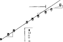
The discretization of curved vortex filaments into straight lines will result in an induced velocity calculation that is, at best, second-order accurate, a problem examined in detail by Bhagwat & Leishman (2001b) and Gupta & Leishman (2004). This result can be seen from Fig. 10.28, which shows a plot of the L2-norm (rms) of the error in the reconstruction of the induced velocity using straight-line segmentation for a vortex ring, a singly-infinite helix with a helical pitch p and a skewed helix with a skew angle f. The induced velocity for a vortex ring was calculated using the exact solution (see Section 10.7.5) and the solution for the finest numerical discretization is comparable up to seven decimal places. The error in the induced velocity for the helical vortex was calculated with respect to the finest discretization because there is no exact solution for the induced velocity from a helix. It is apparent that the order of accuracy of the reconstructed velocity field does not depend on the helical pitch and both the skewed and unskewed helix follow the quadratic trend for A0 < 2.5°, indicating second-order accuracy. This gives high confidence in the straight-line segmentation approach for the general modeling of helicopter rotor wakes.
1
![]()
![]()


![]()
 0.1
0.1
 |
10le 10’7 10’8
0.01 0.1 1 10 " 100
Angular discretization, Дір (deg.)
Figure 10.28 L2-norm for the relative error in the induced axial velocity in the z = 0 plane of a vortex ring, unskewed and skewed helical vortex (skew angle /3 = 30°) with helical pitch p = 0.1.
10.7.1 Governing Equations for the Convecting Vortex Wake
A description of the vorticity field in the rotor wake is governed by the 3-D, incompressible Navier-Stokes equations, which in a Lagrangian form can be written as
~ = (a) • V)V + . (10.49)
strain diffusion
This equation defines the change of vorticity of a fluid element moving with the flow in terms of the instantaneous value of vorticity, со, and the local velocity field V. The term on the left-hand side of Eq. 10.49 represents advection (convection), with the two terms on the right-hand side being a strain or “stretching” term and viscous diffusion term, respectively. In many practical problems, it can be justified that viscous phenomena will be confined to much smaller length scales compared to potential flow phenomena. Therefore, vortex methods use discrete line vortices to represent concentrated lines of vorticity. Under these conditions, Helmholtz’s second law states that the vortex lines move as material lines at the local velocity, V)OC. In the discretized problem, this convection criteria is applied to all of the collocation points that have been specified along the lengths of all the vortex lines (see Fig. 10.27 previously). If we consider a single element of a trailed vortex filament, the fundamental equation describing the transport of a point on the filament is
= Vioc(r, t), r(t = 0) = r0, (10.50)
dt
where r = r(t) = r(xfrw, xfb) is the position vector of a point on the filament at a time (or wake age ij/w) that was trailed from the blade when it was at an azimuth angle xj/b – The term? o is simply an initial condition. This equation is the fundamental equation for the free-vortex wake method or the free-vortex method (FVM). (See Section 14.4 for the fundamental principles behind the derivation of Eq. 10.50.)
Because the wake position vector r is both a function of fb and fw then the derivative on the left-hand side of Eq. 10.50 can be expanded to give
![]()
![]() dr(fb, fw) _ dr / dfw Jkr^ / dfb
dr(fb, fw) _ dr / dfw Jkr^ / dfb
dt dfw dt J dfb V dt
This equation can be simplified by noting that the time derivatives are
dfw _ dfb _ й dt dt
Therefore, in blade fixed coordinates the fundamental equation describing the position vector of the vortex filament is
![]() dr
dr
dfw
This is a first-order, quasi-linear, hyperbolic, partial differential equation (PDE). The homogeneous portion of the equation (the left-hand side) is the linear wave equation. However, the right-hand side is, in general, a nonlinear function mainly because of the induced effects resulting from the complete wake geometry. By assuming that every vortex filament is convected through the flow field at the local velocity, a PDE governing the geometry of a single element of the vortex filament can be written as
 ” + ^ ^indl?(fb, fw), Hfj, fw)].
j=1
(10.54)
Notice that the summation is carried out over the total number of trailed vortex filaments, Nv, that contribute to the induced velocity field at any given point. For tip vortices alone then Nv = Nb.
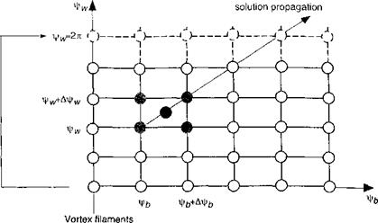
To solve Eq. 10.54 using a numerical scheme, it must be spatially and temporally discretized. This results in a set of simultaneous ODEs. A computational domain can be defined as a discretized grid in time (fb) and space (fw), as shown in Fig. 10.29. Based on such discretizations, the partial differentials in the governing PDE can be approximated using several different types of finite-difference schemes. For example, Crouse & Leishman (1993) have used a “three-point central difference” approximation of the left – hand-side derivatives of Eq. 10.54 about point (fb — Afb/2, fw — Afw/2) using points (‘fb — Afb, fw — Afw) and (i, к), as shown in Fig. 10.29. Bagai & Leishman (1995a, b; 1996) have used a “five-point central difference” scheme, where the derivatives were evaluated at the point (fb — Afb/2, fw — Afw/2) about points {fb, fwX (fb — Afb, k), (i, fw — Afw) and (fb — Afb, fw — A fw) in the discretized computational domain, as also shown in Fig. 10.29.
The induced velocity, Vin(j, in Eq. 10.54 can be determined using the Biot-Savart law (Eq. 10.27) with
л r-Vf,. v-v, , ч1 1 f Tvdfwj x (r(fb, fw)-r(fj, fw))
Vind [r(fb, fw), r(fj, fw)J = — / ——— pr-.—- ——– zq—– -—r3—— ,
4?r J I r(fb, fw) – r(fj, fw) I3
(10.55)
where r(fb, fw) is the point in the flow field influenced by the yth vortex at location r(fj, fw) that has strength Г», The geometry of each element of a discretized vortex
|
|
|
Enforcement of periodicity in a relaxation scheme |
|
Direction of |
|
attached to blades |
|
at г|)£=0 |
|
Figure 10.29 Discretized computational domain for the free-vortex wake problem. |
filament is governed by one of these equations, and the velocity term on the right-hand side couples the equations together. This means that the equations for all of the filaments must be solved simultaneously, and this is a primary expense of the FVM.
Notice that the singular nature of the Biot-Savart law can be avoided by replacing the induced velocity field of the individual vortices with a model with a desingularized core, as discussed previously. Remember that this may also include a core growth (vorticity diffusion) model. The results for the wake geometry and induced velocity field thus obtained are probably qualitatively accurate no matter what vortex model is used. Yet, the quantitative errors associated with the wake model can only be determined though correlation studies with experiments documenting both the wake geometry and the induced velocity field, and caution should always be employed.


