CHARACTERISTICS OF SMALL ASPECT RATIO WINGS
The flow around the tips of a low aspect ratio wing has a greater influence on the operating characteristics than for wings with A = 5 and above. Thus for low aspect ratio wings, the procedures and data given in Chapters MI and XV do not apply. In this chapter low aspect ratio wings with rectangular, tapered and round planforms will be considered. Included will be wings with swept leading and trailing edges. Those classes of wings with delta type planforms will be considered in the next chapter. Small or low aspect ratio wings are defined as those with A < 3. Between A = 3 and 4 the aspect ratio is defined as the intermediate type.
The lift curve slope of low aspect ratio wings increases with angle of attack up to the stall angle rather than remaining linear as in the case of conventional wings. The increase in slope is a secondary effect that takes place over and above the basic circulation lift slope. In the treatment of low A’wings, first the basic slope characteristics will be covered and then the secondary non linear effects.
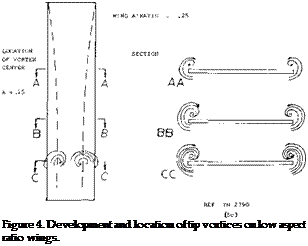
FLOW MECHANISM. The lifting-line theory given in Chapter III represents very well wings with aspect ratios above A = 5. In the case of a wing having a chord which is long in comparison to, or let’s say longer than the span, wings with small aspect ratios, the trailing edge of the wing is exposed to a flow which has been deflected by the leading edge. In this manner the airfoil sections of any finite-span wing are placed within a field of streamlines which are curved in proportion to the permanent deflection (downwash) produced by their own lift. In other words, the chord and curvature are large so that the ratio of the chord in the radius of the stream curvature is also large. As a consequence, the airfoil sections lose lift, their sectional lift-curve slope is less than in two – dimensional flow and the lift angle of the average section is increased. Of course, the induced angle is also increased corresponding to C [_ /А as in larger aspect ratios.
![]()
![]()
1. BASIC LIFT CURVE SLOPE
When considering the theory for determining the performance of small aspect ratio wings the conventional lifting line concept can no longer be used because of the long chord to span ratio. Thus, the lift cannot be assumed to act on a line and must be spread out over the surface of the airfoil. Also, the influence of the lateral edges (a minor effect in larger aspect ratios) becomes more and more predominant as the aspect ratio approaches zero. As in the “straight wing” chapter, small aspect ratios rectangular lifting surfaces with sharp lateral edges are found to be very effective.
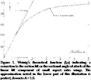
Lifting Surface. Several attempts (1) have been made to extend the lifting-line theory into the range of small aspect ratios or to replace it by so-called lifting – surface theory which accounts for the effect of the wing chord upon the lifting characteristics. One such theory is presented as follows: According to (l, a) the sections of rectangular low-A’ratio wings are aerodynamically in the same position as those in a two-dimensional cascade of airfoils. This analogy amounts to replacing the wing surface by a large number of lifting lines. Disregarding those near the leading edge, an individual airfoil or vane in that cascade develops less lift per unit of angle of attack than in free flow (that is, less than one airfoil alone) because of the downwash already produced by the other vanes located ahead. The average two-dimensional lift – curve slope is reduced accordingly to:
dCL /doL,
where the subscript 42’ indicates the two-dimensional sectional angle of attack required and the correction factor к is
к = (A/2a)tanh(2a/a) (2)
as plotted in figure 1.
SLENDER WINGS. Below A = 1 the factor as in figure 1 is simply
к = 0.5 A/a = 0.5 “A” (3)
The resulting sectional “lift angle” in this range from equations 1 and 3 is
do(z /dCL = 1/ (rr A) (4)
This is also equal to the induced lift angle as in Chapter
III. The geometric angle required is the combination of the induced and two-dimensional angle, and is
da /dCL = 2/rr(A) or dCL/da = 0.5ТГ A (5)
in radians
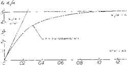
As shown in figure 2, the equations 4 and 5 indicate that below А я* 1 with к = 0.5 “A”, da^ /da = 0.5
and/or (X = 2 & і. The physical meaning of this result is that the final downwash angle £ = 2 occ is reached before the trailing edge of such wings. Cutting off some piece from this edge does not, therefore, reduce the lift for a given span (considering only small values of the lift coefficient). This conclusion can be formulated by referring the lift coefficient to the “span area” b, rather
than to the conventional wing area. For CLb = L/q b^ we thus obtain dCLb //da = rr/2 = constant, which shows that the linear lift of such wings (with A between 0 and a maximum of 1, and at “small” lift coefficients) is independent of their chord. This fact is also the reason that the factor ‘a’, the slope of the lift curve, no longer apears in equation (5). If there are any viscous (boundary-layer) losses, there are many airfoils farther downstream in the cascade which can make up for those losses.
Another theoretical treatment (l, i) of low aspect ratio wings takes into account the flow about the lateral edges. This is done by considering the flow of the airfoil of the low aspect ratio wing as two dimensional when viewed in cross section perpendicular to the longitudinal axis. This flow superposed on the original stream leads to the same result as given in equation 5. The analysis was done by first considering pointed v/ings and showing that no lift is developed downstream of the section with the longest span. This is a necessary condition to satisfy the Kutta condition. Thus only the flow ahead of the section influences the lift at any station and not the flow downstream as in high aspect ratio wing theory. This concept also leads to the equation for the induced drag coefficient
CDl = o’ /2 in radians (6)

(1) Small-aspect-ratio linear wing theory:
(a) Weining, Small Span, Lufo 1936, 405; NACA TM 1151.
(b) Weissinger, Yearbk D Lufo 1940 p 1-145; ZWB Rpt FB 1553 (1942), see NACA TM 1553; Tech Berichte ZWB 1943; ZWB Rpt UM 1392 (1944); Math Nachrichten 1949 p 46; ZFW 1956 p 225; see NACA TM Г120 and TN 3476.
(c) Falkner, ARC RM 1910 (1943) and 2596 (1948).
(d) Jones, Correction for Chord, NACA TN 817 (1941).
(e) Lawrence, Journal Aeron Sciences 1951 p 683.
(0 Kuchemann, Straight & Swept, ARC RM 2935 (1956).
(g) Pistolesi, 3/4 Chord Principle, Conf Lil’thal Ges Lufo 1937 p 214; applied by Weissinger (l, b).
(h) Taylor, Lifting Surface, ARC RM 3051 (1957).
(i) Jones, Properties of Low-Aspect-Ratio Pointed Wings, NACA TR 835.
|
|
||||||||||||||||||||||||||
Lift-Curve Slope. Writing the angle in degrees equation (5) reads:
A value of (1 + лЬ/Ъ) ~ (1 + 2 Д b/b) ^ 0.8 has been used in figure 3 to obtain the lift-curve slope of “round” wings from experimental data below A = 1.
dCL /dtf° = TT[130]A/360 = 0.0274 A. (7)
This function is well confirmed in figure 3 by experimental results on thin rectangular plates. The presented points have carefully been determined as tangents of the lift-curve slopes in the vicinity of C L = 0. In some cases (not plotted) these tangents are not readily available; the theory then serves to understand such experimental data. Up to about A = 2.5 lifting characteristics of sharp-edged rectangular wings can be approximated in form cf their lift angle
dc* /dCL = (36.5/A) + 2 A @ A 2.5 (8)
HIGHER ASPECT RATIOS. The hyperbolic tangent as in equation (2) is tabulated in mathematical or engineering handbooks. Up to an argument “x” = 6 , or = 0.1, tan“x” = sin“x”. The hyperbolic tanh function reaches unity at “x” = 360°, or more precisely at “x” = °o. As the factor к varies between (0.5 “A”) at A below unity, and 1.0 at A oo the angle ratio ( oq/oe ) varies between 0.5 and (2/“A”). Within the range between A ^ 1, and = 5 or 10, a transition takes place from the low A’ratio to the lifting-line function. Using a = 0.9, and the induced angle (20/A), we can use for sharp-edged rectangular wings the same equation as in Chapter III:
|
dtf" /dC, = 10 + (8/A2 ) + (20/A) (10) Experimental points, plotted in figure 3, in the form of the lift-curve slope, confirm this function very well. |
|
|||
|
|||
|
|||
|
|||
 |
|
||
|
|||
|
|||
|
|||
|
|||
|
|||
|
|||
|
|
||
|
|||
|
|
||
|
|||
|
|||

![]()
 x SHARP RECTANGULAR PLATES ■PROFILED RECTANG, SQUARE ENDS & PROFILED DELTA WINGS V0012 DELTA WINGS, BRUNSWICK DPROFILED RECTANG, ROUNDED EDGES О ROUNDED AND ROUND WINGS WTAPERED WINGS, SQUARE ENDS – TAPERED AND ROUNDED • SHARP ELLIPTICAL PLATES AVA + RECTANGULAR W’ROUND EDGES A RECTANGULAR PLATES D-1374
Figure 3. Linear lift-curve slope (at samll lift coefficients) of wings (and plates) as a function of their aspect ratio.
Round Tip Wings. We have found that Ab values for round and rounded tip wings are constant in the form of ( лЬ/Ь) for small A’ratios, equation 8 and in the form of (дЬ/с) for larger aspect ratios. In between these extremes there must be a transition. Mathematically this transition can be accomplished by putting
![]()
 ( ab/c). = ( Able) / VT+2/а" (11)
where (.) indicates the value as in small A’ratios. Note that at A—0, there will be ( Ab/b) = ( дЬ/с)/ V 2 = constant. — We have empirically found that n = 3 is suitable; and that above A = 2, constant values ( дЬ/с) can be used, as for example those listed in various illustrations in Chapter III, without further correction. As in that chapter, the lift angle of typical round tip type wings, is
doc /dCL = 10 + (10/A2 ) + (26/A) (12)
as plotted in figure 3. A “corection” to lifting-line theory, for round planforms, is proposed in (l, d). Using again a = 0.9, this formulation gives results between those for the sharp-rectangular and the “round” wings as in figure 3. We prefer equations 10 and 12, giving us a distinction between two extreme shapes of otherwise straight wings.
(4) Theoretical Analysis non-linear lift small A’ratios:
(a) Bollay, At Zero Aspect Ratio, Zts Ang Ma:h Mech 1939 p 21; also in J Aeron Sci 1936/37 p 294.
(b) Empirical, see NACA TN 2044 & 3430, T Memo 1151.
(c) Theoretical considerations (J Aeron Sci 195 3 p 430, 1954 p 134 & 690) indicate a term Ci_~ Such a trend may account for the type of increase as in figure 7 between A = 0 and 0.5.
(d) Attempts at analyzing mechanism and lift due to the lateral-edge vortices of delta wings are also found in J Aeron Sci 1954 p 212 & 649; see also Weissinger, ZFW 1956 p 225 and Mangier, R Soc London Proc Ser A 1959 p 200.
(e) Brown, Delta Wings, NACA TN 3430 (1955).
(f) Gersten, Non-Linear Theory, ZFW 1957 p 276 and Ybk WGL 1958 p 25.
(g) Lamar Leading-Edge-Suction Analogy around side edges NASA TR R-428.
(5) Experimental investigation of rectangular wings:
(a) Winter, Plates and Wings of Short Span, Forschung 1935 p 40 & 67; Translation NACA T Memo 798.
(b) Zimmerman, Clark-Y Airfoils, NACA T Rpt 431 (1932); see also J Aeron Sci 1935 p 156.
(c) Wadlin, Hydrodynamic Rectangular Plates, NACA TN 2790, TN 3079 & 3249 or T Rpt 1246 (1955).
(d) AVA Gottingen, Ergebnisse I & III (1921/27).
(e) Scholz, Forschung Ing’Wesen 1949/50 p 85.
(f) Bartlett, Edge Shape, J Aeron Sci 1955 p 517
(g) Weinstein, Planing Plate, NACA TN 2981 (195 3).
(h) Brebner, Series of Wings, RAE (1965); AD-48 0253.
(i) Campbell, Small A’Ratios, ARC RM 3142 (I960).


