Example optimum load distributions Planar wake
As shown in Section 5.8.1, the elliptical load distribution is optimum for the case of a planar wake with a fixed span. However, in many aircraft applications a more relevant constraint is not on the span but on the root bending moment, since this dominates the wing’s structural weight which offsets induced drag reductions.
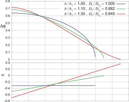
To illustrate this tradeoff, Figure 5.16 shows three load distributions for three different specified spans, each having the same lift and root bending moment. Increasing the span reduces Di significantly, even though the resulting load distributions are very “sub-optimal” in a fixed-span sense. Referring to the Fourier Di expression (5.71), the increase in the span b more than overcomes the increased parameter S which measures how much the loading deviates from elliptical.
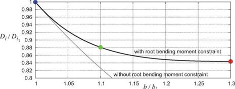
Figure 5.17 shows the relative Di for a continuous range of spans for the flat-wing case with constrained bending moment. With no bending moment constraint, the optimum loading is elliptical for any span, and the induced drag then scales simply as Di ~ 1/b2, indicated by the thin line in Figure 5.17.
|
|
0 0.2 0.4 0.6 0.8 1 1.2 1.4
2y / b1
Figure 5.16: Optimum Ap(y) load distributions and corresponding w(y) normal velocity distributions for three specified spans, all with the same specified lift and root bending moment. The baseline elliptic-loading case has span bi and induced drag Dil.
|
Figure 5.17: Induced drag versus span, with fixed lift and root bending moment, relative to baseline case. The three symbols correspond to the three cases in Figure 5.16. Thin line is the result Di/Dii = (b/b1)-2 for elliptical loading for all spans, which is optimal in the absence of abending moment constraint. |


