EXAMPLE—STABILITY AUGMENTATION SYSTEM FOR STOL AIRPLANE
In Sec. 9.8, where we considered an example STOL airplane, we found that the spiral mode was unstable, with an uncomfortably short time to double. We remarked there that a feedback stability augmentation system might be useful. How should we proceed to synthethize such a system? We can choose any of (/3, p, r) as variables to sense, and feedback functions of them [cf. (11.2,1)] to produce command signals for the aileron and/or rudder. But which variables shall we choose and what functions of them shall we use? Here the “flight dynamicist’s approach” of looking at the feedback control system as a way of modifying the aerodynamic derivatives (Sec. 11.1) is helpful. The full set of synthetic changes that can be made in the six lateral moment derivatives is described by the relations
(11.4Д)
where [&y] is the 2×3 matrix of feedback gains, i.e.
Thus for example,
Equations (11.4,2) are written in dimensional rather than nondimensional form, since the sensing devices used to generate the feedback signals would ordinarily operate on the dimensional physical variables.
These relations must now be applied with good engineering judgment. Stumbling about blindly in the six-dimensional parameter space of the к. и is not a satisfactory way to find the solution. First, the number of nonzero k{j must be kept to a minimum, since each one entails extra hardware or circuitry, adding to weight, cost, complexity, and failure probability. Second, the engineer must take advantage of his understanding of the system and of the
fault to be corrected. Here the fault is that the spiral mode is unstable, the other two modes being stable. We know that the criterion for spiral stability in horizontal flight is (9.7,6)
«Ух “ > 0 (H.4,4)
and that it must be the violation of this criterion that is the cause of the instability. On examining Table 9.9—for example at Cw = 4.0—we find the left hand side of (11.4,3) to be
(,010)(—.25) – (,67)(.120) < 0
We also observe that there is no hope of correcting the situation without changing the sign of one of the four derivatives. In fact the one to which our attention is naturally directed is Ct, which is here positive, but is ordinarily negative for “well-behaved” airplanes. A “synthetic” Glfi of the required sign can be introduced by aileron feedback of the form
= ^11^> ^11 > 0
In fact, an attempt at a solution based on this sideslip feedback for Gw = 4.0 was unsuccessful. When ku was made large enough to stabilize the spiral mode, the lateral oscillation was driven unstable. Now we observe from
(9.7,13) that Cn is the main factor available to control the damping of the lateral oscillation and hence an increase in |(7n | is indicated. This is also beneficial in meeting (11.4,4) when combined with a change of sign of Glfi. We therefore choose a second nonzero gain, k23, so that the control deflections are given by
Д<5Г = k23r k23 > 0 (11.4,5)
The control derivatives assumed for this example, representative of those that pertain to a deflected sHpstream configuration, are
@ida = —-13/rad = -.30/rad
GnSa = +.04/rad C4r = +.04/rad
With these derivatives, and a control law given by (11.4,5), values of к1г and k23 can readily be found that eliminate the instability in the spiral mode while maintaining a stable lateral oscillation. In point of fact it is only a little more difficult in this case to incorporate a more realistic feedback law than the simple gains of (11.4,5). Consequently the example has not been computed with (11.4,5) but rather by assuming that each control actuator is a first-order dynamic system of fast response time. The corresponding control equations used were
which implies that the time constants of the aileron and rudder position servos are, respectively, xo and – A – sec> that there are zero time lags in the fj and r sensors, and that the steady-state gains are
Aileron: = Аи/10 deg/deg
Rudder: Jczs = K23/12 deg/(deg/sec)
Equations (11.4,6) are now incorporated into the basic lateral equations of motion to yield the final mathematical system. After converting (11.4,6) to nondimensional form, we get the result (11.4,7). The eigenvalues of (11.4,7)
|
Dp |
CVft |
Cyr 1 |
Cwe |
0 |
0 |
P |
||
|
2p |
2(1 |
2ц A |
2(1 |
|||||
|
Dp |
Civ |
Clr |
Cha |
chr |
A |
|||
|
І’х |
К |
V Jx |
0 |
r. |
rx |
V |
||
|
Dr |
Gn0 |
Gnv |
Cn0 |
0 |
Сща |
C«Sr |
л |
|
|
= |
n |
V xz |
V J-Z |
n |
Ц |
|||
|
D<j> |
0 |
1 A |
0 |
0 |
0 |
0 |
Ф |
|
|
DSa |
Kllt* |
0 |
0 |
0 |
— Ш* |
0 |
Дй« |
|
|
Ddr |
0 |
0 |
-^■23 A |
0 |
0 |
— 12г* |
ASr |
|
(11.4,7) |
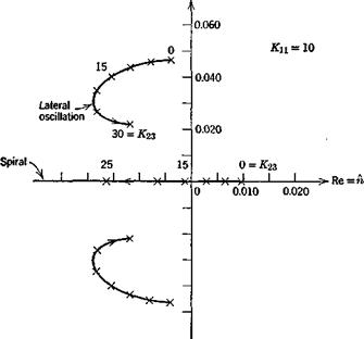
were calculated for ranges of Kn and K23, and a typical root locus is shown on Fig. 11.7. There is a substantial range of practical gains for which stability is achieved. For example for KX1 = 10, K23 = 20, the spiral and Dutch-roll characteristics are
Spiral: fj^ = 7.4sec
Oscillation: T = 12.4 sec, = .21 cycles
The corresponding control gains are, respectively, 1 deg/deg for the aileron, and 1.67 deg/(deg/sec) for the rudder. These are both quite modest, and would not likely present any exceptional problems of control design.
|
Im =a>
Fig; 11.7 Root loci for stability augmentation system. |


