FLIGHT ON ILS GLIDE SLOPE
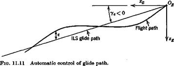
In the above analysis, we assumed that the airplane was under the control of an ideal autopilot that kept the height error exactly zero. A more realistic model incorporates a feedback control that senses height error and actu ates the elevatorf in response (see Fig. 11.11). The time lag associated with response of height to elevator input may be expected to lead to stability characteristics significantly different from those of the simple model.
Let us assume then that the airplane is making an automatically controlled approach on ILS. That is, a radio beam defines the glide path, and the pitch autopilot is coupled to the radio signal in such a way that height error is sensed and actuates the elevator. The autopilot and control system are
|
|
|
t A still more sophisticated system uses control of thrust as well as of elevator. This is capable of producing better system performance provided that thrust responds quickly enough to the control command. |
relatively fast-acting compared to the pitch response of the vehicle, so we may reasonably assume a simple gain for the transfer function of these elements. Thus the mathematical model is obtained from (5.13,19) with the additional control law
Да, = + К2І (11.5,7)
where є is the height error and we have included both proportional and rate terms.
For the class of airplane considered, the standard glide slope is about 2 to 3°, so little error is introduced by using the equations for ye = 0, and this we do. The height error is defined as
e = zE. — zE (11.5,8)
where zE. is the commanded altitude. Thus combining (11.5,7 and 8) we get A8e = KyzE — K2iE + КггЕ. + K2iE, which in nondimensional form is
Ай, = – К, І zE – K2VeDzE + kJzEi + K2VeDzE. (11.5,9)
h 2i
From the last of (5.13,19), for ye = 0, we have
Dze = — Ay = Aoc — A6
from which we get
A<5e = – K, UE – K2Ve(Ax – AO) + КЛ zE( + K2VeDzEj (11.5,10)
2i
For the control inputs in (5.13,19) we take
ACTc = AGBe = ACLc = 0
and AGmc = Gmi Ade (11.5,11)
We assume additionally that a number of derivatives are zero (as in Sec. 9.1),
1Л’ 0Dr=0Lr = 0M7 = GLt = GZet= 0
The basic system derived from (5.13,19) is then 5×5, with variables AV, Ax, q, Ad, zE, with AGmc eliminated via (11.5,10 and 11). The result is given


