Flow Separation
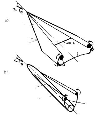
Flow separation is defined by the local violation of the boundary-layer criteria (constant pressure in wall-normal direction, approximately surface-parallel flow), by the convective transport of vorticity away from the body surface and the subsequent formation of vortex sheets and vortices behind or above/behind a flight vehicle. This definition goes beyond the classical view on separation. It implies that separation can be present at any flight vehicle just because any flight vehicle is of finite length. However, it is justified, because behind or above/behind every flight vehicle with aerodynamic lift always vortex phenomena (vortex sheets and vortices) are present, see Fig. 9.1.
We distinguish two principle types of separation [3]:
– type a: flow-off separation,
– type b: squeeze-off separation (the classical separation).
Flow-off separation happens at sharp edges, which can be leading edges or trailing edges, Fig. 9.1 a). Squeeze-off separation typically occurs at regular surface portions, due to the pressure field of the external inviscid flow, Fig.
9.1 a) and b).
In both cases always two boundary layers are involved. In the case of flow – off separation the boundary layers from the two sides of the sharp edge (at a wing trailing or leading edge those from above and below the wing) flow off the edge and merge into the near-wake. In the case of squeeze-off separation the boundary layers squeeze each other off the same surface [3].
While in two-dimensional flow squeeze-off separation is defined by vanishing skin friction—actually by the change of sign of the wall shear stress
 vortex
Fig. 9.1. Schematic of separation types, and resulting vortex sheets and vortices at basic configurations at large—typical for re-entry flight—angles of attack [4]: a) wing with large leading-edge (LE) sweep, b) fuselage. In both cases secondary and higher-order separation phenomena at the leeward side are not indicated, also not indicated are the separation phenomena at the rear end of the fuselage. Flow-off separation is indicated as type a, squeeze-off separation as type b.
tw —such a clear criterion is not available for three-dimensional flow. In threedimensional attached viscous flow tw vanishes only in a few singular points on the body surface, for instance at the Blunt Delta Wing (BDW) in the forward stagnation point, see, e. g., Fig. 3.16, but also at singular points in the separation region [6].[153] Along three-dimensional separation lines, as well as attachment lines, Figs. 3.16 and 3.17, skin friction does not vanish [1].
In [1] criteria for three-dimensional separation are proposed. A practical indication for a three-dimensional squeeze-off separation line is the converging skin-friction line pattern, Fig. 3.6, and for a three-dimensional attachment line the diverging pattern, Fig. 3.5, see also Figs. 3.16 and 3.17.
Fig. 9.1 shows where on configuration elements, typical for hypersonic flight vehicles, the two types of separation occur. At a delta wing with large leading-edge sweep and sufficiently large angle of attack [7], we observe squeeze-off separation at round leading edges, which are typical for hypersonic vehicles, Fig. 9.1 a). The primary squeeze-off separation line can lie well on the upper side of the wing, as we have seen in the case of the BDW, which has a rather large leading-edge radius, Figs. 3.17 and 3.19. If the leading-edge radius is very small—the sharp swept leading edge is the limiting case—we have flow-off separation at the leading edge, Fig. 9.1 a), type a.
At the sharp trailing edge of such a generic configuration we find flow-off separation, which we find also at sharp trailing edges of stabilization and control surfaces. At round fuselages, Fig. 9.1 b), and also at blunt trailing edges—which can be found at hypersonic flight vehicles—always squeeze-off separation occurs. If local separation (see below) occurs, we have squeeze-off separation with subsequent reattachment.
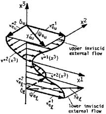
The near-wake resulting from flow-off separation at the trailing edge of a lifting wing in steady sub-critical flight has the general properties indicated in Fig. 9.2.[154] The profile of the velocity component п*1(ж3) resembles the classical wake behind an airfoil at sub-sonic speed. It is characterized by kinematically inactive vorticity, and represents locally the viscous drag (due to the skin friction) and the pressure drag (form drag), i. e., the total drag of the airfoil [4].
This kinematically inactive wake type would appear also if we have a blunt trailing edge with a von Karman type of vortex shedding. (For the latter see, e. g., [8].) Such trailing edges are sometimes employed at hypersonic wings or control surfaces in order to cope locally with the otherwise high thermal loads. This can be done without much loss of aerodynamic efficiency, if the boundary layers, which flow off the trailing edge, are sufficiently thick.
In Fig. 9.2 the s-shape like profile of the velocity component v*2(x3)—in contrast to v*1 (x3)—is kinematically active and represents locally the induced drag. The angles ФЄи and Феі vary in the span-wise direction of the wing’s trailing edge. In sub-critical flow we have ФЄи = —Феі [1].
These near-wake properties are found in principle regardless of the type of separation (flow-off or squeeze-off separation), and whether vortex layers or vortex feeding layers are present, Fig. 9.1.
Flow separation can also be categorized according to its extent [1]:
— local separation,
— global separation.
Local separation is given, for instance, if the flow separates and reattaches locally (separation bubbles or separation occurring at a ramp or a
|
Fig. 9.2. Schematic of a three-dimensional near-wake of a lifting wing in steady sub-critical flight [4]. The coordinates x1 and x2 are tangential to the skeleton surface of the wake, x3 is straight and normal to it. v*1 and v*2 are the tangential velocity components. Su and Sl denote the upper and the lower edge of the wake, where the inviscid flow vectors v£u and have the inclinations ФЄи and Фч against the x1 – axis. |
two-dimensional control surface, e. g., Fig. 9.6 c)), or if it is confined otherwise to a small region. Shock/boundary-layer interaction, if the shock is strong enough, leads to local separation. In any case local separation is characterized by a rather local influence on the flow past a flight vehicle.[155]
Flow-off separation always is global separation with global influence on the vehicle’s flow field. The canonical phenomena are the induced angle of attack and the induced drag, respectively, which appear on a lifting wing.
The basis of this categorization is the locality principle [1]. It says basically that a local change of the flow field, for instance due to separation, but also of the body geometry, affects the flow field only locally and downstream of that location (see in this context also Sub-Section 7.1.4). Of course, due to the strong interaction the inviscid flow field is changed, but then it is a question of its spatial characteristic properties (elliptic, hyperbolic), whether or not upstream changes are induced. Such changes can be significant, if the wake of the body is kinematically active. Then we have global separation, which leads, for instance, to the mentioned induced drag of classical aerodynamics.
At a lifting delta wing, the leeward side vortices, Fig. 9.1 a), induce an additional lift increment, the non-linear lift. This does not violate the locality principle, because this is not an upstream effect. At hypersonic flight with large angle of attack (re-entry flight) leeward side vortices are present, too, see, e. g., Section 3.3, but the hypersonic shadow effect (see the introduction to Chapter 6), annuls the non-linear lift. Also phenomena like vortex breakdown, see, e. g., [9, 10], do not play a role at such flight.
The location of squeeze-off separation (type b) primarily is governed by the pressure field and the Reynolds number of the flow. This is important in particular for the primary separation at the well rounded wing leading edges of RV’s. The Mach number may have an effect as well as possibly also noise and surface vibrations, see, e. g., the numerical study of local separation cases at the border of the continuum regime in [11]. High-temperature real-gas effects probably have an influence on separation only via their influence on the flow field as such.
Global separation regions, for instance the leeward side flow field of the basic configurations shown in Fig. 9.1, exhibit also embedded secondary and even tertiary separation (and attachment) phenomena, as well as cross-flow shocks, which can interact with the attached surface-flow portions, causing local separation phenomena.[156] A classification of such flows is given, e. g., in [12, 13].
In closing this section some words about the simulation of separated flows. In ground-facility simulation it is a question for both global and local separation, whether the Mach and Reynolds number capabilities of the facility permit to get proper results, and whether the flow to be simulated in reality is laminar or turbulent. The surface temperature has an influence, but the question is, how large it is for which flow classes.[157]
Computational simulation today is able to give results of high accuracy as long as the flow is laminar throughout the whole flow field. It also permits to quantify the influence of the surface temperature, if it is governed by radiation cooling. Usually the radiation-adiabatic surface is a good approximation. If a larger amount of heat enters the wall, a flow/structure coupling becomes necessary, see, e. g., [14]. However, if laminar-turbulent transition is present, computational capabilities become limited. The influence of the location and form of the transition zone may possibly be parameterized, at least for simple configurations.
Computational simulation of attached turbulent flow has, more or less, the same status as that for laminar flow. Turbulent separation, which can be highly unsteady, only now is becoming treatable with hybrid or zonal RANS/LES methods, Section 8.5. We show as an example two results of an numerical investigation by V. Statnikov et al. [15] of the experimental study of Mо = 6 rocket base flow by D. Saile et al. [16].
The generic rocket configuration has a cylindrical main body with a rounded conical nose. The base either is blunt or has a nozzle dummy extended from the base. A vertical strut at the top of the main body is the support of the wind tunnel model, which is modeled in the computation, too. The flow parameters and some geometrical parameters are given in Table 9.1.
|
Table 9.1. Flow parameters of the generic rocket configuration [15]. D is the diameter, the length is 0.4724 m. The nozzle dummy has a length of 0.1296 m and a diameter of 0.043 m.
|
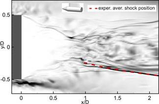
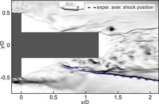
We give only two characteristic results of the numerical investigation in Figs. 9.3 and 9.4, which show time-averaged numerical schlieren pictures. Indicated in each picture is the location of the recompression shock.
|
Fig. 9.3. Numerical schlieren picture in the symmetry plane of the—above inserted—blunt base configuration [15]. The recompression shock found in the experiment [16] is indicated by the broken line. |
In both cases the good agreement with the experimentally found position of the shock is evident. We note in particular the satisfactory to good agreement between the computed and measured base pressure spectra for both cases [15].
An obviously almost not known tool to investigate the structures of ordinary separation flows, but also of shock/boundary-layer interaction flows, and to establish credibility of results of experimental and numerical simulations are topological considerations, see, e. g., [6, 17], and also [18].
|
Fig. 9.4. Numerical schlieren picture in the symmetry plane of the—above inserted—nozzle dummy configuration [15]. The recompression shock found in the experiment [16] is indicated by the broken line. |
Consider the skin-friction patterns at the windward and at the leeward side of the HERMES configuration in Fig. 9.5. The singular points on the vehicle surface can be connected via topological rules, see the examples given in [1] and [14]. Further a surface normal to the longitudinal axis of the vehicle yields a Poincare surface in which attachment and separation lines (lines with diverging and converging skin-friction line patterns in Fig. 9.5) show up as half-saddles, which also, together with off-surface singular points, can be connected with the help of topological rules. We have given an example in Sub-Section 3.3.2.
|
Fig. 9.5. Computed skin-friction lines at the windward side (left) and the leeward side (right) of the HERMES configuration in a ground-simulation facility situation at = 10, pt = 10 bar, Tt = 1,100 K, Tw = 300 K, a = 30°, laminar flow [19]. |
We do not analyze the skin-friction line patterns shown in Fig. 9.5. The reader is encouraged to do this on his own. In this way he can check the plausibility of the computed patterns, and can gain missing information, and indications of, for instance, hot-spot situations at attachment lines on radiation cooled surfaces, see in this regard also Section 3.3.


