Our heavyweight helicopter equal in the world does not have
In Rostov started production of the most load-lifting rotary-wing car The Russian holding «Helicopt[...]

Everything about aircrafts and helicopters. News and events in aviation worldwide. Civil, transportation, military helicopters and airplanes.

Everything about aircrafts and helicopters. News and events in aviation worldwide. Civil, transportation, military helicopters and airplanes.

Everything about aircrafts and helicopters. News and events in aviation worldwide. Civil, transportation, military helicopters and airplanes.

Everything about aircrafts and helicopters. News and events in aviation worldwide. Civil, transportation, military helicopters and airplanes.


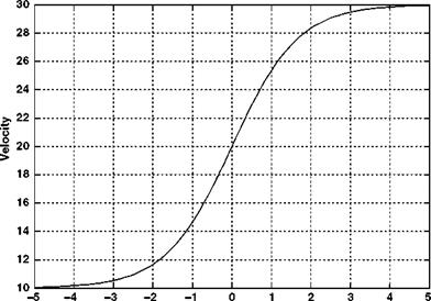
In order to investigate the concept, the velocity variation down the length of the streamtube needs to be modelled. Actuator disc (momentum) theory cannot give a precise solution to this velocity variation; however, a realistic and simple velocity variation can be defined thus:
V = Vc + Vi + Vi • tanh(k0 (2.32)
where s is the vertical location variable with the origin at the rotor disc centre – positive downwards; h is a distance defining the extent of the contracting streamtube above and below the rotor disc; and k is a factor which adjusts the severity of the contraction. The hyperbolic tangent function was used because of its asymptotic behaviour so the streamtube finishes as a cylinder far above and below the rotor disc.
Having defined the velocity variation, it is straightforward to determine the pressure variation: the pressure jump at the rotor disc means that the variation must be referenced to either end of the streamtube, far above and below the rotor, where the air pressure returns to ambient. So, using Bernoulli’s equation, we find that the pressure is given by the following two expressions (two are needed as described above).
|
Pi+; PVC = P + 2 Py2 |
Above rotor:
pi + 2 r(vC+2Vi)2 = p + 2 pv2
![]()
p-Pi (VC + 2Vi)2-V2
p 2
If we finally define a pressure coefficient, based on a reference air velocity of U, we find the following results for the pressure variation for above the rotor (CPu) and below the rotor (CPL):
with the following values:
|
Vz |
10 m/s |
|
Vi |
10 m/s |
|
R |
10 m |
|
U |
10 m/s |
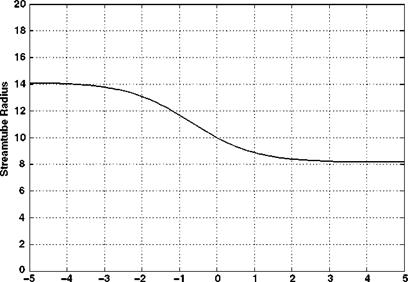
The velocity, streamtube size and the pressure variation are shown in Figures 2.8-2.10.
![]()
|
|
|
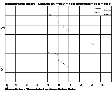 |
The velocity and streamtube radius follow from the foregoing discussion. However, the pressure variation requires some investigation. The pressure line for any location below the rotor lies above that for locations above the rotor. However, it must happen that the overall pressure variation must move, discontinuously, from one solution to the other. It is difficult to justify any movement from one line to another in the free air stream; however, a pressure jump may be successfully argued at the rotor disc. It is this pressure jump that determines the thrust achieved by the rotor and is shown in Figure 2.10.
The above discussion demonstrates the emergence of an actuator disc model which in reality cannot occur. It is not easy to envisage an airflow whose velocity is continuous but also undergoes a discontinuous pressure change at the rotor disc. Therefore one cannot buy an actuator disc; it is purely a conceptual device which describes in fairly good detail the helicopter rotor in axial flight (which includes hover). In the case of climb and hover, this method can be used quite successfully. Unfortunately, this straightforward method has a weakness as it is poor at modelling a descending rotor over a range of descent rates. This will now be investigated.