Models for the Tip Vortex
 |
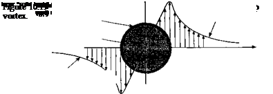
With this general picture of the tip vortex induced velocity field in mind, a model of the tip vortex can now be hypothesized. Tip vortex models used in rotor wake simulations are typically specified in terms of a 2-D tangential (swirl) velocity profile. The other velocity components (the axial and radial) are small and are usually neglected in most applications. This, however, may not be a justifiable assumption at young wake ages. A schematic of a typical distribution of swirl velocity is shown in Fig. 10.19. The inner part of the vortex (the core region) rotates almost as a solid body, whereas the outer part behaves almost as a potential flow. The core radius, rc, is defined as the radial location where Vq is a maximum (i. e., at the core radius r = r/rc = 1). This boundary demarcates the inner (almost purely rotational) flow field from the outer (potential) flow.
 |
The simplest model of a vortex with a finite core is the Rankine vortex [see Lamb (1932)], where the swirl velocity is given by
the Lamb vortex model (Eq. 10.9) can be written as a function of nondimensional radial distance r — r/rc as
![]()
 |
(10.14)
 |
Using a series expansion for the exponential term and ignoring higher order terms, it can be shown that
(10.15)
Because of the assumption of a columnar vortex, the axial and radial components derived by Vatistas et al. (1991) do not strictly apply to trailed vortices. However, a general result for the axial (and radial) components of the velocity for trailed vortices can also be deduced starting from the assumption of Eq. 10.11 and the appropriate form of the governing Navier – Stokes equations applied to a trailing vortex,^ In the first instance, it is reasonable to assume that the induced velocities are dependent only on r and z (i. e., the vortex is assumed to be axisymmetric). The governing Navier-Stokes equations in cylindrical coordinates for incompressible flow are written as
continuity:
 (10.16)
 |
||
r m
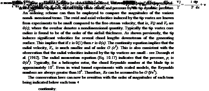
It should be noted that the 0- and г-momentum equations indicate that the swirl and axial velocities have small gradients along the z axis, and are not independent of z. This is consistent with various experimental observations that viscous diffusion is a gradual process and, therefore, the velocity gradients along the time-like z axis are small. It is also observed that the peak axial velocities decrease rapidly at early wake ages, whereas the peak swirl velocities decrease more gradually (~N/z) (i-e., the swirl velocity gradients are small compared to the axial velocity gradients). Using this information, the в – and ^-momentum equations can be written as
![]() dVe, a V, ,
dVe, a V, ,
—-=0[O(c3)] and —i = 0 [0(e2)],
dz dz
and the 0(e2) terms in the ^-momentum equation cancel each other, that is,
The required boundary conditions given by Newman (1959) can be obtained by assuming that the vortex is generated as a “free” vortex, that is, a potential vortex of strength at z = 0, and it diffuses until at large distances the vortex induced velocities become zero. These boundary conditions can be formalized as
1. At z = 0, Ve = Fv/2nr and Vz, Vr = 0. Note that there is a singularity at r = 0.
2. For г > 0, Vg, Vz, Vr 0 for larger.
3. As z —> oo, Ve, Vz, Vr -* 0 for all r.
The governing equations have now been reduced to only two equations (i. e., Eqs. 10.24 and 10.29) but are in terms of three components of velocity, for which there can exist no unique solution. However, with the assumption of the Vatistas swirl velocity model m Eq. 10.11, the axial and radial velocities can be found using Eqs. 10.24 and 10.29. These
components are found to be
where A is a constant related to drag, as mentioned previously.
 |
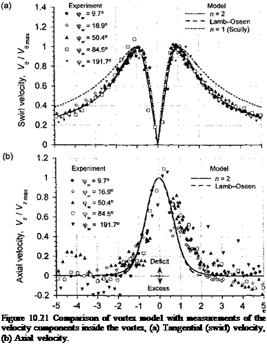
The results from the above analysis of the vortex problem have been compared with some of the experimental measurements shown previously in Fig. 10.18. The time-averaged convection velocity of the tip vortex through the rotor wake has been removed, which puts the measurements into a frame of reference moving with the vortex core. Figure 10.21(a) shows the measured swirl velocities nondimensionalized with respect to the peak velocity and the radial distance with the estimated core radius. The measurements show a good correlation with the Lamb-Oseen and n = 2 swirl velocity models, and they also confirm
Distance from vortex center, r! r
the self-similar nature of the velocity field surrounding the tip vortex. Some deviations may be attributed to the presence of extraneous wake vorticity from the inboard part of the blade and other blades that are present in the measurement grid. The commonly used n = 1 or Scully (1975) vortex model seems to be a less accurate descriptor of the velocity field, at least in this case. Figure 10.21(b) shows corresponding comparisons for the nondimensional axial velocities. Again, the Lamb-Oseen and n = 2 model are found to give good agreement with the measured velocities. Like the swirl velocity, the axial velocity profiles also exhibit a self-similarity, though perhaps not as strongly. The fluctuations in the measured axial velocities are probably a result of small asymmetries in the tip vortices. However, the generally good agreement with the measurements suggests the validity of the assumptions inherent in this very basic analysis of the trailed vortex problem.


