Prescribed Wake Models for Hovering Flight
For hovering flight, generalized prescribed vortex wake models have been developed to enable predictions of the inflow through the disk, but without the expense and uncertainties associated with explicitly calculating the force-free positions of the wake. These models prescribe the locations of the rotor tip vortices (and sometimes also the inner vortex sheet) as functions of wake age bw on the basis of experimental observations. For hovering flight, generalized prescribed vortex wake models have been developed by Landgrebe (1969, 1971, 1972), Gilmore & Gartshore (1972), Kocureck & Tangier (1976), and Kocureck & Berkowitz (1982).
Landgrebe’s Prescribed Wake Model
![]() Landgrebe (1971, 1972) studied experimentally about seventy subscale helicopter rotor configurations with different combinations of number of blades, rotor solidity, blade
Landgrebe (1971, 1972) studied experimentally about seventy subscale helicopter rotor configurations with different combinations of number of blades, rotor solidity, blade
twist, and blade aspect ratio. On the basis of these experiments, Landgrebe’s model describes the tip vortex geometry by the equations
 (10.56)
and
![]() — = A + (T — Alexnf—
— = A + (T — Alexnf—
R ‘ r ‘
Notice that the vertical displacements are linear with respect to wake age (i. e., they convect axially at a constant velocity), which is consistent with all experiments. At the first blade passage when fu, = 2Tt/Nb, it has been shown previously in Fig. 10.6 that there is a sudden change in the axial convection velocity. This is reflected in the change of the coefficient from k to k2 in the equations describing the axial displacements. The axial settling rates are modeled by the empirical equations
![]() *, = -0.25(Cr/a +0.0016>tw),
*, = -0.25(Cr/a +0.0016>tw),
k2 = -(1.41 + О. О1410№)УСг/2 « -(1 + O. O10tw)/CV,
where the blade twist 0tw is measured in units of degrees. The radial contraction of the wake is smooth and asymptotic. The empirically derived coefficients for the radial contraction are given by A = 0.78 and Л = 0.145 + 21 Cj. Notice that while the theoretical contraction ratio of a rotor wake in hover is 0.707 (see results in Section 2.2.3), in practice the contraction ratio is found experimentally to be consistently closer to 0.78. The vortex sheet trailed by the inner parts of the blade vary linearly with r. The outer end of the sheet (r = 1) is represented by the equations
whereas the inner end of the sheet is represented by
![]()
![]()
![]() (10.61)
(10.61)
The locations of intermediate parts of the sheet are determined by linear interpolation. The empirical coefficients of the sheet coordinates are described by
![]() Ku=i = —2.2л/Ст/2,
Ku=i = —2.2л/Ст/2,
 (10.63)
(10.64)
|
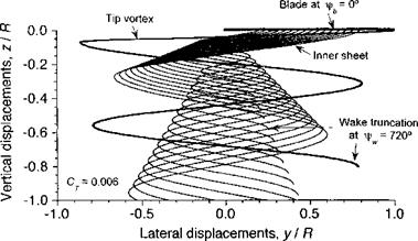
Figure 10.30 Representative prescribed hovering wake based on Landgrebe’s model. Nh = 2; СУ = 0.006; 0tw = 0°. |
A representative wake geometry in hovering flight based on Landgrebe’s model is shown in Fig. 10.30. The wake for two revolutions of the rotor are shown to convey the relative differences in the convection rates of the sheet versus that of the tip vortex. Notice that the outer edge of the inner sheet convects axially downward at a rate that is approximately twice that of the tip vortex, a result alluded to previously in Section 10.3.2. In the hover state, it is found that the inclusion of the vortex sheet is usually necessary to enable good predictions of induced inflow and rotor performance.


