
Our heavyweight helicopter equal in the world does not have
In Rostov started production of the most load-lifting rotary-wing car The Russian holding «Helicopt[...]

Everything about aircrafts and helicopters. News and events in aviation worldwide. Civil, transportation, military helicopters and airplanes.

Everything about aircrafts and helicopters. News and events in aviation worldwide. Civil, transportation, military helicopters and airplanes.

Everything about aircrafts and helicopters. News and events in aviation worldwide. Civil, transportation, military helicopters and airplanes.

Everything about aircrafts and helicopters. News and events in aviation worldwide. Civil, transportation, military helicopters and airplanes.


To avoid cumbersome algebra, consideration will be confined in this section to the simplest case of the extreme ground effect for a wing with a straight trailing edge. In the steady flow problem, the velocity potential does not depend on time. Consequently, there are no unsteady free vortices in the wake, and the corresponding flow model is substantially simplified.
Recalling the formulas for induced downwash aw at the trailing edge, one should mention that to the lowest order of approximation aw ~ aWl, and downwash does not depend on the abscissa x of the point in the wake, i. e.,
aWl=h(^(0,Z). (3.57)
Therefore, if the wing is in steady motion and its relative clearance is small, then at all points of the wake with the same z coordinate, the downwash is “almost”[14] the same as that behind the trailing edge. This important circumstance allows writing formula (2.109) for determining the induced drag coefficient (accounting for suction force) for the case of small relative ground clearances in the following way:
= | J ¥>h (°, z) (0, z) dz, (3.58)
where, as earlier, S is the reference area of the wing related to the square of the root chord. In addition, the condition of optimality of the wing (in the extreme ground effect) can be written as a requirement that the downwash distribution at the trailing edge should be uniform in the spanwise direction.
As indicated in 3.1, in the case of the extreme ground effect, it is sufficient to solve the following problem:
• Boundary conditions:
(px =0 at the leading edge Zi,
pi = 2^^- =0 at the trailing edge. (3.60)
ox
For a flat wing, y[ = 6 = 6/h, where в is a pitch angle.
The lift and moment coefflcients can be calculated by using the formula
|
2 /**/2 Cy = — ірг (0, z) dz; & J-l/2 |
(3.61) |
|
2 f f d<ph (x, z) m* = sJJsx Эх dxd2- |
(3.62) |
|
We consider the example of a rectangular wing, for which the domain S is a rectangle 0 < x < 1, z < Л/2, where Л is the aspect ratio. At first, suppose that the wing is flat, so that the right-hand side of equation (3.59) is equal to 6 = 6/h, where в is the angle of pitch. We seek (px in the form |
|
|
oo <Ph = 9 ^2 Xn(x) cos qnz, n=0 |
(3.63) |
|
where qn = 7г(2п + 1)/A. Expression (3.63) should vanish for Noting that 4 ^ (-l)n cos qnz |
z = ±Л/2. |
|
and substituting (3.63) in Poisson equation (3.59), we obtain an ordinary differential equation for functions Xn(x) |
|
|
X" o2X – 4(“1)n Лп ЯпЛП — л • |
(3.64) |
A general solution of (3.64) can be sought in the form
sinh qnx cosh qnx 4(-l)n
Xn{x) = an————- + bn——————– V-/–
cosh Qji cosh q>n qn
Bearing in mind that the boundary conditions for the function фг at the ends of the interval 0 < x < 1 are
Vll(l,2)=0, -^-(0,^ = 0,
we obtain the conditions for the functions Xn(x) at the ends of the segment 0 < x < 1:
 *;(o)=o,
Finally, we find the following expression for the channel flow velocity potential:

 (—l)n /cosh(/nx
The distribution of aerodynamic loading to this order of approximation is

 |
д(рг 8в ^ (-l)n sinh</nx
A £ґ0 € cosh qn
In Fig. 3.8 examples are given of the distribution of parameter h(p) /в, which characterizes the aerodynamic loading, for rectangular wings of aspect ratios Л = 1 and Л = 3. The loading distributions have been calculated on the basis of the leading-order solution.
|
16 в tanh</n tanh(</n/2) ~h* |
The lift coefficient can be calculated as

![]()
![]() mz
mz
= 1C ~jf (ta–h-— + tanh tanh у – l). (3.66)
hX пҐоV 9" 2
The induced drag coefficient is
/-Ї h Ґ tr\9Vlwn u 802 ^ tanh2g„tanh2(g„/2)
C" = – A L, n(0’Z)^(0′ = £———— —•
As/i<l, the formulas obtained above are valid for practical arbitrary aspect ratio h « A < oo. The distance of the center of pressure from the leading edge is defined by the ratio xp = —mzjCy and mz and Cy are determined by (3.65) and (3.66).
If A —» oo, we obtain the formulas for a flat plate of an infinite aspect ratio:
Cy = -, mz = – —, Xp = Cx. = 0. (3.68)
It follows from (3.68) that for a plate of an infinite aspect ratio moving in very close proximity to the ground plane, the center of pressure is located at a distance one-third of the chord from the leading edge. Recall that in unbounded flow the center of pressure of a flat plate (A = oo) is located at one-fourth of the chord from the leading edge.[15]
For a small aspect ratio A —> 0, the general formulas yield the following results:
 (3.69)
16aA3
![]() /і7Г5 ’
/і7Г5 ’
96A
7Г°
 |
Some results of calculations of the aerodynamic coefficients of a rectangular wing versus the aspect ratio A are plotted in Fig. 3.9 with ten terms retained in the corresponding series. The terms of the series in expressions (3.65)-(3.67) decrease with the increment of n as 1/(2n + l)4. For not very large A, it is practically sufficient to retain one term, so that
 |
in Fig. 3.10, where the results of the present theory for h -> 0 are compared with those obtained by Belotserkovsky and Scripatch [130] for h = oo.
It is easy to determine the suction force coefficient Cs. Calculating the factor а і
4(9 ^ (-l)n,
— > —5— tanh qn cos qnz,
h ‘ qf.
n=о ™
and substituting this expression in formula (2.113) with є = в and /і* ~ h, we obtain the suction force coefficient in the form
![]() ^ _ г<вва2 _ 86,2 ^ tanh2 qn c’-c• 6
^ _ г<вва2 _ 86,2 ^ tanh2 qn c’-c• 6
n=0 71
In the limiting cases,
![]() for Л —^ 0, Cs —
for Л —^ 0, Cs —
Comparing the latter formula with (3.70), one can see that for the case of the extreme ground effect, quite similarly to the case of unbounded flow, realization of suction force on a wing of small aspect ratio reduces the induced drag by half.
Now, assume a spanwise distribution of the pitch angle of the wing sections in the form
e(z) = eo0(z).
The solution of problem (3.59)-(3.60) can be readily constructed in the following form:
|
во Sn (cosh qnx 7t(2n + 1) li = T У, “о (————– Г———- 1 cos qnz, qn =—————————– . h^oq[16]Kcos hqn J Л • Corresponding lift coefficient: oo £ • Induced drag coefficient: |
• Flow potential:
![]() n – в<> V" tanh2 tanh2(9„/2)
n – в<> V" tanh2 tanh2(9„/2)
x>~ h q3 ■
n=0
where 0n are determined by the following formula
2 fx/2
0n = – г 0(z) cos qnz dz.
л J-X/2
Following Widnall and Barrows [40], consider the case of the wing of semielliptic planform with a straight trailing edge. In this case the domain S is represented by a semiellipse with axes equal to 1 and I/2, where l is the relative span of the wing. Equation (3.59) and the boundary conditions (3.60) are satisfied, if the function <рг is sought in the form
<Ph = d(x2 + -Ji l)> (3.76)
where d is a constant. Substituting (3.76) in Poisson equation (3.59), in the case of a flat semielliptic wing,
![]() ві2
ві2
d~ 2h{l2+4Y
Taking into account that for vanishing ground clearances the distribution of circulation spanwise is equal to
m2 / 422
r{z) ^ -<Ph (o, z) – 2/l(/2 + 4) (! ~ ir)«
one can see that the loading of a semielliptic wing has a parabolic distribution spanwise.
The lift coefficient becomes
![]() m2
m2
v 37xh(l2 4- 4) ’
![]() For a semicircular wing (l = 2) the lift coefficient is two times less than for an semielliptic wing of an infinite aspect ratio (l oo). It is interesting that the limiting results for l —У oo do not coincide with those for the two-dimensional problem because in the limit the wing retains a semielliptic planform. In fact, in the two-dimensional case,
For a semicircular wing (l = 2) the lift coefficient is two times less than for an semielliptic wing of an infinite aspect ratio (l oo). It is interesting that the limiting results for l —У oo do not coincide with those for the two-dimensional problem because in the limit the wing retains a semielliptic planform. In fact, in the two-dimensional case,
Ci
whereas here for l —> oo,
It is worthwhile to mention that for a semielliptic wing in the extreme ground effect, the induced downwash in the wake is constant spanwise:
_ 46> :wi _ /2 + 4
![]() so that such a wing is optimal for any aspect ratio.[17] The induced drag coefficient is given by
so that such a wing is optimal for any aspect ratio.[17] The induced drag coefficient is given by
![]() 2вСу _ Cl _ 4/2 Л
2вСу _ Cl _ 4/2 Л
/2 + 4-7гАМ’ ^“Зт^А h~12h’
Calculating the factor a taking into account the equation of an ellipse, and using expression (2.113), one finds the suction force coefficient of a semielliptic wing in the form

![]() Cs = Cene92
Cs = Cene92
Use has been made of the formula A = 4Z/7г for the aspect ratio of a semielliptic wing. It is easy to check that expressions (3.78), (3.80) and (3.81) comply with the evident requirement Cx. = 9Cy — Cs for a flat wing. The influence of the aspect ratio on the lift coefficient and the induced drag coefficient for semielliptic flat wing in the extreme ground effect is illustrated in Fig. 3.11 in comparison with a rectangular wing.
Now, we can turn over to the case of a rectangular wing with a flap. Let the wing of aspect ratio A have a flap whose chord is equal to bf and deflection angle is 9f. The domain S bounded by the wing planform contour consists of two rectangular subdomains Si (bf < x < 1, |z| < A/2) and S2 (0 < x < bf, z < A/2). Due to the linear formulation, the effect of the flap deflection angle can be studied separately from that of the pitch. Therefore,
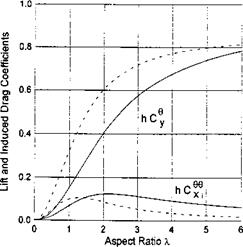 Fig. 3.11. The influence of the planform of the wing on the lift and induced drag coefficients for different magnitudes of the aspect ratio (dashed lines correspond to a semielliptic flat wing; solid lines to a rectangular flat wing).
where the coefficients an and bn are equal to
![]() 4(-l)r
4(-l)r
{1 +tanh^„i)„tanh[gn(l – bf)]}Agn’
The lift coefficient can be found as
n _ д M _ tanhgnbf tanh(g„bf/2) + tanh[gTI(l – bf)] tanhg„b/
![]()
 |
у f у h2 q*{l +tanh[q„(l – 6f)] tanhq„6f}
(3.82)
The coefficient of the longitudinal moment with respect to the hinge axis of the flap is
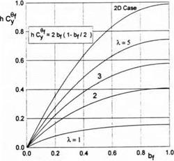
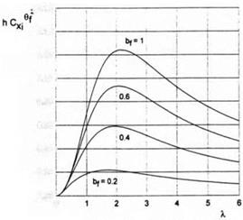 Fig. 3.12. The lift coefficient of a rectangular wing in the extreme ground effect versus the relative chord of the flap for different magnitudes of the aspect ratio.
![]()
![]() Fig. 3.13. The induced drag coefficient of a rectangular wing in the extreme ground effect versus the relative chord of the flap for different magnitudes of the aspect ratio.
Fig. 3.13. The induced drag coefficient of a rectangular wing in the extreme ground effect versus the relative chord of the flap for different magnitudes of the aspect ratio.
m. = S, mi = § f; _
hX Qn t cosh qnbf qn )
![]()
![]() Qn 2 J
Qn 2 J
The coefficient of the induced drag
Q = У’ (tanh(gnbf/2) + tanh[gn(l – 6f)]}2 tanh2 qnb{ X’ 9n(! + tanh[g„(l – bf) tanhqvA}2 ‘
Figures 3.12 and 3.13 illustrate the dependence of the parameters hCy1, and hCXi/6f upon the aspect ratio of the wing for different chords of the flap.
