WAKE ROLLUP
The conditions that the wake will move with the local streamlines (and carry no loads) were introduced as early as Section 4.7 for thin lifting surfaces and later in Section 9.3 when discussing the wake model for panel methods. From the steady-state flow point of view, the shape of the wake is not known, and the process of finding the proper wake shape (wake rollup) is often denoted as a “slight nonlinearity” in the solution process. Typical remedies to this problem are:
Prescribe wake shape. This is done in Chapters 4, 8, and 11 for the lifting line and lifting surface type of solution (where the wake is placed on the z = 0 plane). A more refined alternative of this option is to prescribe the wake shape based on flow visualizations. This approach is very helpful when analyzing multielement wings where, for example, in the case of a two-element airfoil the wake of the main airfoil is very close to the trailing-edge flap upper surface.
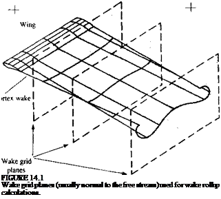
Wake relaxation. This is a process used by several steady-state numerical solutions, and to demonstrate the principle of this method let us follow the approach used in the code VSAERO.92,12 11 The initial wake geometry is specified by the programmer (usually as a planar wake extending backward from the trailing edge) and then several wake grid planes (normal to the free stream) are established, as shown in Fig. 14.1. For the first iteration, the flowfield over the wing and the initial wake shape are calculated using the method described in Section 12.5.
For the second iteration the velocity induced by the wing and wake (n, v, w)h at each of the wake points (formed by the intersection between the
Trailing vc
 wake grid planes and the wake lines) is calculated. Next, the wake points are moved with the local induced velocity (see Fig. 14.1) by
![]() (Ax, Ay, Az), = (u, v, w), At
(Ax, Ay, Az), = (u, v, w), At
(Some methods, for simplicity, will move the wake in the wake grid plane only. If this is done in the free-stream coordinate system, then the wake grid lies in the x = const, plane and only (Ay, Az)t are required.) In Eq. (14.1) At is an artificial time parameter and its value can be approximated as
 (14.2)
where Ax/ is the distance of the wake grid plane from the trailing edge (or between the wake grid planes) and К has values between 0.5 and 5. Once all the wake points have been moved, due to the local induced velocity, the flow is computed with the new wake geometry and the second iteration cycle (or wake relaxation iteration) has been completed.
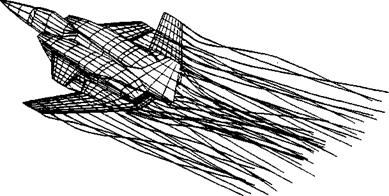
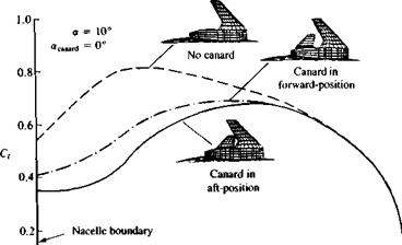
These wake relaxation iterations can be continued until convergence is obtained or when sufficient wake rollup has been achieved (decision made by the programmer). Since there is always a risk that by too many iterations the wake can reach levels of nonphysical rollup (where the sum of the iteration time steps E At is much larger than AxJQJ) it is recommended to limit the number of wake rollup iterations to less than three. Results of such a procedure (after two wake iterations) are presented in Fig. 14.2. Here the VSAERO9 21211 code was used and the interaction between a close-coupled wing-canard configuration was calculated. Figure 14.3 shows the effect of the
|
FIGURE 14.2 Wing and canard wake rollup after two iterations, using the wake relaxation method of Ref. 12.11 (program VSAERO9’2,12 "). From Katz, J., “Evaluation of an Aerodynamic Load Prediction Method on a STOL Fighter Configuration", AIAA Paper No. 86-0590, 1986. Reprinted with permission. Copyright AIAA. |
|
|
01______ і_______ I_______ 1_______ I———- 1———- 1———-
0.3 0.4 0.5 0.6 0.7 0.8 0.9 1.0
2 у lb
FIGURE 14.3
Effect of canard position on wing’s spanwise loading. From Katz, J., “Evaluation of an Aerodynamic Load Prediction Method on a STOL Fighter Configuration”, AIAA Papier No. 86-0590, 1986. Reprinted with permission. Copyright AIAA.
canard on the wing’s spanwise loading. Note the noticeable effect of the canard and its wake, which induces a downwash at the wing root area and thereby reduces its lift there. The proper placing of the wake in such cases of closely spaced lifting surfaces is critical and estimation of the wake motion is important for the solution.
Time-stepping method. This approach was demonstrated in Chapter 13 (Sections 13.8.2 and 13.10) and in principle is similar to the wake relaxation method, but now the time step is directly related to the motion. (Therefore, the apparent “slight nonlinearity” does not exist.) From the point of view of computations, the number of wake points increases with time and, for example, for N wake lines during К time steps approximately NK/2 wake point velocity computations are required. When using the wake relaxation approach, even for the first iteration, all wake grids are used and therefore NK such velocity calculations are required. Thus, even for steady-state flows, this time-stepping wake rollup method may require less computational effort.
As an example for this wake rollup calculation consider the rollup of a single horseshoe vortex. In this case, the wing bound vortex is modeled by a
|
|
|
observed calculated^ (^^* = 0.25. -~»80) " f> о |
FIGURE 14.4
Instability of a pair of trailing vortices, and comparison between calculated and observed vortex formations. Figure 14.4a shows the wake behind the airplane after its passage and Fig. 14.46 depicts the Crow instability which is shown later at a distance of about 80 wing spans. More details about such calculations can be found in Rossow, V. J., Journal of Aircraft, vol. 24, no. 7, 1987, pp. 433-440. Photo from Ref. 14.1. Reprinted with permission of AIAA and Meteorology Research, Inc. Photo originally appeared in Smith, T. B. and Beemer, К. M., “Contrail Studies of Jet Aircraft," MRI Report, April 1959.
single vortex line that sheds two wake line segments of length Q „ At at its tips during each time step. As this shedding process continues, the two long trailing vortices are formed, but because of the instability of these two vortex lines a sinusoidal pattern will develop. This instability was first analyzed by Crow14 1 who presented the photographs appearing in Fig. 14.4 in Ref. 14.1. The numerical solution presented in Fig. 14.4a is obtained by using only one panel in the method described in Section 13.12, and the above instability is also visible in the computation. Calculations such as this one and that of Fig. 13.29 indicate that this approach for calculating the rollup of vortex sheets yields satisfactory results (at least when modeling trailing wakes behind wings).
As a closing remark to most of the wake rollup modeling efforts, we must emphasize that the velocity induced by a vortex point or line is singular (see, e. g., Fig. 3.8a). Therefore, an artificial vortex core (or cut-off distance) must be defined for the purpose of numerical solutions. One possibility is to define the self-induced influence as zero within this radius; however, in some methods a solid-body rotation model is used within this core (which is very similar to Fig. 2.11 with є being the core size).


