AN UNSTRUCTURED APPROACH
|
|
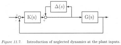
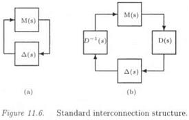
Let the closed loop of Figure 11.5, where K(s) and G(s) are the controller and the plant. A block of neglected dynamics A(s)is added at the plant inputs. This closed loop is first equivalently transformed into the standard interconnection structure M(s) – Д(в) of Figure П. б.а. M(s) is the transfer matrix seen by the model perturbation A(s) in Figure 11.5. A necessary and sufficient condition of stability is provided by the small gain theorem at frequency u:
|
|
It was assumed above that A(s) is an unstructured model perturbation. Nevertheless, a specific structure can be given a posteriori to Д(з):
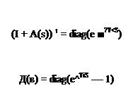
I + Д(з) = diag(e ^’)
or:
The idea is thus to introduce phases фі in order to compute a MIMO phase margin with equation (11.20). When combining equations (11.20) and (11.22), one obtains:
Let:
A MIMO phase margin at frequency w is:
 фі < 2 Arcsin(a{<jj)/2) Vi If the following structure is now given to Д(з):
I + Д(з) = diag{e~ns)
and using фі = шті, a MIMO delay margin at frequency ш is:
![]()
![]() Arcsin(a(u>) / 2)
Arcsin(a(u>) / 2)
Remarks:
(i) ifa(cu) > 2, the MIMO phase margin is ± 180 degrees, and the MIMO delay margin is infinite.
(ii)
 |
||
MIMO phase or delay margins can also be computed with an inverse model perturbation at the plant inputs (see Figure 11.7). In this case, the delays are to be introduced as:
Direct model perturbations rather account for high frequency model uncertainties, whereas inverse model perturbations rather represent low frequency model uncertainties (Doyle et al., 1982). As a consequence, better estimates of the delay margin can be expected with an inverse (resp. direct) model perturbation at low (resp. high) frequencies (see section
3.
 |
).


