APPLICATION TO THE MISSILE
As a preliminary, when analyzing the robustness of a control law in the presence of time delays, three frequency bands are classically to be distinguished, namely the low, medium and high frequency bands. In the low frequency band, even if the MIMO phase margin ДФ is not especially high, the associated MIMO delay margin Д r = Д Ф / r is generally high because of the low values of ui. In the high frequency band, the rolloff properties of the controller generally ensure an infinite delay margin. The lowest values of the MIMO delay margin are consequently obtained at medium frequencies.
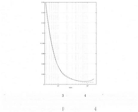
![]() Missile example with 3 delays and 4 parametric uncertainties – compai
Missile example with 3 delays and 4 parametric uncertainties – compai
ison of the conservatism of the small gain approach and of the approach of section 2
The issue in this section is to compute the robust delay margin in the presence of aerodynamic uncertainties in the 4 stability derivatives Za, Ma, Zv and Mr). 3 time delays are introduced at the missile input and at the 2 outputs. A frequency gridding is used, with 100 points between 0.01 rad/s and 200 rad/s. With the exception of the last two points (181 rad/s and 200 rad/s), a finite robust delay margin is obtained with the small gain approach and a direct or inverse model perturbation. Figure 11.9 shows the results obtained with the small gain approach and
with the approach of section 2.: in an obvious way, this approach gives better results than the small gain one.
 More precisely, let Лгі(ш) (resp. Дт2(ш)) the lower bound of the robust delay margin obtained with the small gain approach and a direct (resp. inverse) model perturbation. Let then Д д ( т ) the lower bound of the robust delay margin obtained with the approach of section 2.. On Figure 11.9, the solid line corresponds to Дтз(си) while the dashed line corresponds to max(Ari(o;)^T2(ta)).
solid (resp. dash-dotted) line represents the lower bound of the robust delay margin obtained with the small gain approach and a direct (resp. inverse) model perturbation – the frequency range on the x axis is 3.5 rad/s, 200 rad/s.
The reduced conservatism of the approach of section 2. can be further illustrated on Figure 11.10, which represents on a logarithmic scale
(solid line) and (dashed line): Д гзД ) , i. e. the margin provided by
the approach of section 2., is greater than the one provided by the small gain approach at all frequencies. Note moreover on Figure 11.10 that the result provided by the small gain approach and an inverse (resp. direct) model perturbation is indeed better at low (resp. high) frequencies.
The minimal value of Дг(ш) = тах(Ат(ш),Ат2(иі)) over the fre
quency range is computed as 5.8 ms at з = 8 1.3 rad/s (lower bound of the robust delay margin obtained with the small gain approach – see Figure 11.11).
|
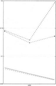
Figure 11.12. Missile example with 3 delays and 4 parametric uncertainties – the solid (resp. dash-dotted) line represents the lower bound of the robust delay margin obtained with the small gain approach and a direct (resp. inverse) model perturbation – the two dashed lines represent the lower and upper bounds of the robust delay margin obtained with the approach of section 2. – the frequency range on the x axis is [6 rad/s, 7.4 rad/s]. |
One then focuses on the results obtained with the approach of section 2.. The upper bound of the robust delay margin is infinite, except in two frequency intervals [6 rad/s, 7.4 rad/s] and [34.3 rad/s, 44.7 rad/s]. These two intervals are consequently emphasized in figures 11.12 and 11.13. Note the small gap between the lower and upper bounds of the robust delay margin obtained with the approach of section 2., at least near the critical frequency. When computing the minimal value of these lower and upper bounds over the frequency range, an accurate estimate of the robust delay margin is obtained as [8.8 ms, 9.0 ms] at ш = 38.56 rad/s.
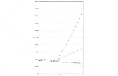
Note in Figure 11.13 that the result provided by the small gain approach is nearly non conservative at the critical frequency u> = 38.56 rad/s However, the lower bound of the robust delay margin obtained with the small gain approach still decreases for ш > 38.56 rad/s, so that the minimal value over the frequency range of the lower bound provided by the small gain approach is obtained at ui = 81.3 rad/s. Much better results are thus obtained with the approach of section 2..
|
Figure 11.13. Missile example with 3 delays and 4 parametric uncertainties – the solid (resp. dash-dotted) line represents the lower bound of the robust delay margin obtained with the small gain approach and a direct (resp. inverse) model perturbation – the two dashed lines represent the lower and upper bounds of the robust delay margin obtained with the approach of section 2. – the frequency range on the x axis is [34.3 rad/s, 44.7 rad/s|. |
4. CONCLUSION
The approaches of sections 2. and 3. are compared:
■ At least in the missile example, better results are obtained with the approach of section 2.. This is logical, since a much finer description of the delay frequency response is used.
■ The small gain approach of section 3. only provides a lower bound of the robust delay margin, while the approach of section 2. provides an interval of this margin. A destabilizing value is moreover obtained for the mixed model perturbation and time delays. The interest of the method of section 2. is also to provide a measure of the conservatism of a lower bound of the robust delay margin.
■ Nevertheless, real (resp. complex) scalars represent the uncertainty in the delay frequency response in section 2. (resp. section 3.). The presence of complex scalars improve the regularity of the ц plot as a function of frequency ш. As a consequence, the peaks on the ц plot are more narrow with the approach of section 2., so that a finer frequency gridding is to be used.
The small gain approach of section 3. is easier to implement, since it essentially reduces to a skewed ц problem. The associated algorithm is polynomial time. Conversely, the approach of section 2. is possibly less easy to implement, but better results are expected and an interval of the robust delay margin is obtained instead of just a lower bound. Note that the algorithm in this book is exponential time, but that a polynomial time version could be derived (Ferreres et al., 1996b).


