Near-field loads
Once the surface vortex sheet strength 7(s,£) distribution is known from the solution of the lifting-surface problem as described above, the resulting pressure jump or equivalently the loading can be determined using the Bernoulli equation as follows.
aV = Vu – Vi = 7 x П
V0 = ^(V« + V/) = (V7)0 – (U + Oxr)
The ()u and ()i subscripts denote the upper and lower sides of the surface, as also used in Section 5.4 for a wake. Here (VY)a is the velocity of the entire vortex sheet configuration, averaged between two field points on the two sides of the sheet. An equivalent version of the loading expression (6.21) is
Ap n = p Va x Y (6.22)
which in effect is a local Kutta-Joukowsky relation.
 |
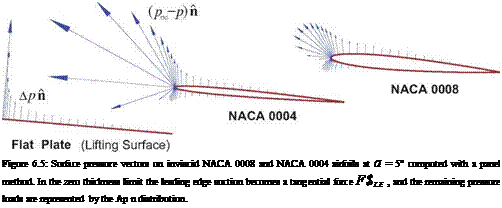
The lifting surface approximation largely neglects the details of the flow in the leading edge region, which consequently requires a special treatment in the force calculations. Figure 6.5 shows the actual (pTO-p) n surface load vectors on 2D inviscid airfoils of different thicknesses. The strongly negative pressure distribution acting on the small leading radius is known as leading edge suction, and is the mechanism by which the pressure drag of the aft-pointing pressure forces over the rest of the airfoil are canceled. In 2D the cancellation is theoretically perfect, while in 3D the cancellation is partial but still very significant. This problem of properly capturing pressure drag was raised previously in the near-field force analysis in Section 5.1.2.
The leading edge suction force can be determined by applying the integral momentum theorem to a control volume enclosing the leading edge point, and assuming that the local vortex sheet strength varies as
![]()
 |
|
Y(x)
where C is now determined from the actual sheet strength y(«4) of the solution, and t is the unit tangential vector pointing ahead of the leading edge, and normal to both n and the leading edge line.
The overall force and moment on the configuration from the normal forces are finally obtained by integration of the pressure loading distribution and also the leading edge suction forces over all the surfaces.
F = Ap n ds d£ + F’Sle ds (6.24)
surfaces Surface JL. E.
M = Ap rx n ds df + / rx FSlb ds (6.25)
surfaces surface L. E.
The integration over the wakes is not performed. The rationale is that a real wake must have Ap = 0 anyway, even if this isn’t quite true in the simplified lifting-surface model in which the wake 7 is assumed to be aligned with X. To get a truly force-free wake in the model would require aligning the wake geometry and its strength 7 with the local Va direction. This would make the lifting surface problem nonlinear, since the geometry of the vortex sheets would then depend on the flow solution itself. All these complications are sidestepped by assuming the fixed X wake direction and simply ignoring the resulting implied wake loads.


