Non-lifting wings at supersonic speeds
6.7 We have already discussed wings in supersonic flows very briefly in section 3.4, and we have used a general relation (3.44), or (4.140), for the wavedrag due to volume, to demonstrate the importance of this contribution to the drag force which occurs when Mq * 1 (see e. g. Fig. 4.75). Now, we want to consider the volume-dependent effects in more detail for sharp-edged slender wings with leading edges which lie well within the Mach cone from the apex, so that Bs/Л <1 , as in Fig.
In the theoretical approaches which are suitable for design purposes, the assumption is usually made that the wing causes only small perturbations.
This also provides the justification for treating thickness effects separately from lift effects. The general potential equation (2.2) or (6.31) is then again linearised:
As before, we may also neglect second-order and higher-order terms in the boundary conditions and fulfil these in the plane z = 0 . Again, in this thin wing theory,
where z = z(x, y) is the equation of the wing surface. If the wing is represented by a distribution of sources, the simplified boundary condition (6.51) is equivalent to the assumption that the source strength is proportional to the normal component of the mainstream velocity at the wing surface. Again,
as before, the wing may also be assumed to be slender if, geometrically, its dimensions in the flight direction are large compared with its dimensions normal to the flight direction; and if, aerodynamically, the leading edges lie well within the Mach cone from the apex. Then (6.50) reduces to
(6.52)
We speak of slender thin-wing theory if the simplified boundary conditions (6.51) are used, and of slender-body theory if the boundary conditions are fulfilled on the surface. Thus we have again three possible theoretical approaches which correspond to the cases tabulated in the previous section.
There is a considerable body of theoretical work, and we refer to papers by G N Ward (1949), F Keune (1952), M A Heaslet & H Lomax (1953), H Lomax (1955),
К Oswatitsch & F Keune (1955), M A Heaslet & J R Spreiter (1956), M J Lighthill
(1956) , J R Spreiter & A Y Alksne (1958), E Y C Sun (1964), and D Hummel
(1968) , where derivations of the basic relations may be found. A full account of the general theory has been given by W R Sears (1955). For the present purpose, we follow the work of J Weber (1957), (1959), W T Lord & G G Brebner (1959), and J H В Smith et al. (1965), which is specifically concerned with the kind of shapes we have in mind for practical applications.
 |
Consider first the problem of calculating the pressure distribution over the surface of a wing of given shape, according to linear thin-^wing theory. A unique solution of (6.50), which satisfies the boundary conditions (6.51), is given by
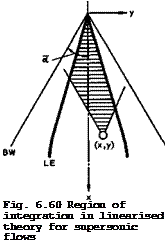
i. e. over the Mach forecone of the pivotal point, as indicated by the shaded area in Fig. 6.60. The flow at that point is not influenced by the part of the wing which lies behind the forecone. Apart from the region of integration, (6.53) differs from the corresponding relation (6.45) for subsonic flow by a factor 2: in supersonic flow, it takes a source strength four times the local surface slope to produce a certain thickness. The pressure coefficient can then be determined from the linearised Bernoulli equation (6.46), as before.
An accurate method for obtaining numerical answers has been developed by J H В Smith et al. (1965). Using an extension of finite-difference operator techniques, A Roberts & К Rundle (1973) have derived another method which can also be applied to the inverse problem of determining the shape of the wing to have a prescribed pressure distribution. M С P Firmin (1963) and (1966) provided yet another specific method as well as experimental results in the transonic speed range, which demonstrated that the transition from subsonic to supersonic flow proceeded smoothly as the Mach number was increased.
D G Randall (1958) and (1959) has introduced specific improvements to render the solutions uniformly valid when dealing with the trailing-edge region in
 |
subsonic flow and with the leading-edge region in supersonic flow when the leading edge lies close to the Mach cone from the apex.
Consider next the problem of calculating the pressure distribution according to stender-body theory. Equation (6.52) in the two variables у and z together with the boundary condition of zero normal velocity at the wing surface, determines the potential function ф(х, у,г) except for an additive function of x, which must be obtained in some other way:
ф(х, у,г) = ф|(y, z;x) + Ф2(х) . (6.55)
If the linearised boundary conditions (6.51) are used, the solution for ф| is
+s(x)
Ф,(у, г=0;х) = ^ f In |y – y’|dy’ . (6.56)
0 – s{x)
 |
G N Ward (1949) has determined the function ф2(х) by returning to the complete linearised potential equation (6.50) and satisfying the boundary conditions ф(x, y,z) = 0 and Эф(х, у,г)/Эг = 0 at the Mach cone through the apex. Alternatively, F Keune (1952) has determined ф2(х) by expanding the integral in (6.53) in a power series with respect to the semispan and neglecting higher-order terms. Both arrive at the same result:
can again be calculated from (6.46) for thin wings. Note that the function ф] is independent of Mq, so that ф only varies with Mach number through
Ф2 •
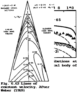
In many practical cases, these approximate theories may give adequate results, but they cannot be relied upon in general* Typical diacve, pan3jie8 which may arise are shown in Figs. 6.61 and 6.62 for two wings of large thickness, one
 —^ SLENDER-BODY THEORY
—– THIN-WING THEORY
 |
AO EXPERIMENT BRITTON
of conical shape and the other non-conical with a sharp trailing edge. Experimental results in Fig. 6.61 by J W Britton (1962) agree quite well with those from slender-body theory when 8s/& is small, but at &s/l = 0.65 this geometrically thick body can obviously no longer be regarded as aerodynamically slender. Further, the thinness assumption does not appear to be justified in this case. In Fig. 6.62, results from thin-wing theories are compared to show the difference which the additional slenderness assumption can make.
Both theories predict quite small velocity increments and the same general type of velocity distribution, with an expansion over the forward part of each spanwise station and a compression over the rear part, but there are discrepancies in the details, especially near the wing tips. J Weber (1957) has discussed the various shortcomings of the theories. A wholly satisfactory theory for calculating pressure distributions, which can also take account of the effects of viscosity, does not yet exist.
 |
These theories have proved useful in predicting the wavedrag due to volume and especially in providing pointers to how to design wings which have a low wavedrag. Within linear thin-wing theory, the overall drag is given by
This calculation of the drag from the shape altogether involves four integrations. Alternatively, the drag may be calculated from the rate of change of momentum in the x-direction through a large cylinder around the body (see sections 3.1 and 3.2). This leads to the supersonic area rule, derived by H Lomax (1955), which gives the same results as those from linear thin-wing theory. It involves the determination of cross-sectional areas in oblique cuts through the body followed by the evaluation of a triple integral.
Following initial work by Th von Karman (1936), F I Frankl & E A Karpovich (1948) and G N Ward (1949) have provided a method for calculating the wave – drag of slender bodies with pointed noses, and M J Lighthill (1955) has applied this to wings with unswept trailing edges for 8s/S, < 1 , with the following result:
![]()
![]()

C,
![]()
![]() (6.59)
(6.59)
where the constant к is given by
+s +s
I I In [~~-‘SyT| e (y)s(y’ )dydy’
![]() (6.61)
(6.61)
and the length і = 1 . The function F(x) and its derivatives have the same meaning as in (6.57). E Eminton (1955) and (1961) and J Weber (1959) have provided practical methods for evaluating the integrals. This relation indicates the important part which the geometry песет the trailing edge has in determining the wavedrag. For pointed bodies of revolution and for wings with cusped trailing edges, F'(l) = 0 , and the drag then does not depend on the Mach number. This is the sonio area rule for smooth bodies. But for wings with non-zero trailing-edge angles, F'(l) =£0 , and the third term in (6.59) then gives a variation of the drag with Mach number, depending on the stream – wise slope of the wing shape at the trailing edge.
Before considering how this fact may be exploited in wing design, we can indicate at last how we arrive at the relation (3.44) or (4.140), which has already been used so often. W Haack (1941) and W R Sears (1947) have derived shapes of bodies of revolution of given length and volume which have the smallest possible wavedrag. One of these is the so-called Sears-Haack body, which is pointed at both ends. Its drag is
This is twice the drag of the von Karman ogive forebody of one half the volume and one half the length. In (4.140), the drag from (6.62) has been used as a standard to measure the drag of any other body or wing, and Kq = 1 indicates that the body or wing has the same drag as the Sears-Haack body of revolution of the same volume and length. We see from (6.59) that the value of the volume-dependent wavedrag factor Kq of wings can vary with Mach number.
We are interested here in sharp-edged delta wings with smooth surfaces. For some of these with simple, but nevertheless interesting, geometry, pressure distributions and wavedrags can be worked out analytically in elosed form (see J Weber (1957)). Such a wing is that proposed by К W Newby (1955), who also calculated pressure distributions in incompressible flow. This wing has biconvex sections in the x-direction; spanwise sections are of rhombic shape so that the thickness-to-chord ratio decreases linearly across the span to zero at the tip. The ordinates of the wing surface are given by
and the cross-sectional area distribution by
F(x) = 12 vol x (1 – x)
![]() Theoretical velocity distributions over the surface of such a wing have already been shown in Fig. 6.62. The value of the wavedrag factor according to slender-body theory is
Theoretical velocity distributions over the surface of such a wing have already been shown in Fig. 6.62. The value of the wavedrag factor according to slender-body theory is
![]() Ko – li (f – І ln 2 – ln 6s/*) •
Ko – li (f – І ln 2 – ln 6s/*) •
For example, Kq = 0.85 for this wing when 6s/A = 0.4, i. e. it is below unity.
Another wing of simple shape has been defined by W T Lord & G G Brebner (1959)
![]() (6.66)
(6.66)
with the so-called "Lord V" area distribution:
![]() F(x) = vol 7×2(l – x)(4 – 6x + 4×2 – x8) .
F(x) = vol 7×2(l – x)(4 – 6x + 4×2 – x8) .
In this case, the value of Kg according to slender-body theory can be approximated by
tr _ ii7 1 + ^.56s/& £o
K0 ” K17 1+ 4es/T • (6*68)
Kq = 0.72 for the same value of 6s/I as for the Newby wing.
These rather low values of Kg call for a more systematic investigation of the effects of the geometry on the wavedrag. We follow here J Weber (1959), who considered a family of wings with the area distribution
F(x) = vol x2(l – x)f(x) , (6.69)
where f(x) is a polynomial, so that, in fact,
N
F(x) = vol x2(l – x) апхП • (6.70)
n=0
To obtain numerical answers, wings with rhombic cross-sections and, therefore, a linear spanwise distribution of the streamwise slope at the trailing edge were chosen:
є(у) = є(0)(1 – J y/s I) , (6.71)
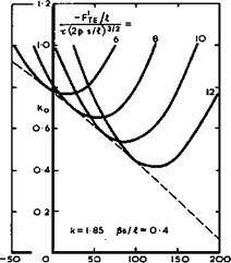
for which к = 1.85 . The drag factor according to slender-body theory can then be written down explicitly and its minimum determined by differentiation with respect to chosen parameters, for given values of s/A and 6s/A. An example is shown in Fig. 6.63 for such a family of wings. The curves for minimum drag are seen to have an envelope which represents the lowest attainable wavedrag within the family considered. The theory predicts values of Kq which are well below unity. (The value of Kq for Newby’s wing lies
LIVE GRAPH
Click here to view
|
x(2p s/03/a Fig. 6.63 The smallest volume-dependent wavedrags of a family of slender wings. After J Weber (1959) |
above the envelope and that for the Lord V area distribution lies close to it.) Kq i-s small when F* and F" at the trailing edge are large.
Although Fig. 6.63 applies only for a particular family, similar general trends have been found also with other families. Much the same curves have been obtained for area distributions which are polynomials of sixth degree (as in Fig. 6.63) and others which are polynomials of eighth degree. The results also indicate that the same values of Кл can be obtained with
* I If v
different values of F*je and Fte » and of x, p, and s/i as long as the volume x(p s/Л)3/2 and the length і are the same. This gives some freedom of choice to the designer to satisfy other conditions. This work also demonstrates very clearly how much more insight into what really matters may be obtained from approximate solutions in closed form rather than from purely numerical solutions obtained by a computer, where the main trends may be difficult to detect and well hidden and may easily be missed altogether.
In all the cases considered so far, the trailing edge is assumed to be sharp and unswept. Equation (6.59) still applies to wings with unswept trailing edges when the trailing edge is blunt (but it excludes the base drag itself), or when a fuselage is combined with the wing (provided that any part of the fuselage behind the trailing edge is cylindrical). In the latter case the expression for the factor к is different. J Weber (I960) has derived numerical values of к for wings with blunt trailing edges and for wings with sharp trailing edges attached to circular-cylindrical bodies in midwing position. Another geometrical feature to be considered is a relatively small angle of sweepbaok of the trailing edge, which, as we have seen, might be beneficial with regard to the lift-dependent drag and for trimming purposes. The effect of swept trailing edges cannot be obtained reliably from slender – body theory. It has been investigated by J C Cooke & J A Beasley (1960) and by J A Beasley (1965), using linear thin-wing theory. These calculations are
much mere laborious and require the evaluation of a four-fold integral. The general result in all the cases considered is that sweeping the trailing edge of a given wing increases the zero-lift wavedrag, if the length and volume are held constant. The increase may be as much as 20% for a sweepback angle of about 35°. F Keune et al. (1975) have investigated slender wings with various thickness distributions, with a view to reducing the wavedrag. Variational methods have been applied by A Nastase (1974), (1975) to determine the optimum optimorum’ of the wavedrag due to volume. It appears that her examples give values of Ко near 0.35 at $s/£ – 0.75 . In the same series of papers she also studied the corresponding problem for the lift-dependent drag.
The main question of practical importance is how far the predicted low values of Kq are physically realistic. Obviously, the very low values cannot be realised in practice. Short of an appeal to experiment, several checks can be made in the design of a wing. First, the result can be inspected to see whether the assumptions made in the theory have been violated. Various errors which may arise in the theories have been discussed by J Weber (1957) and (1959). Second, the pressure distribution can, and should, be calculated to see whether the flow implied looks at least physically plausible and, in particular, whether the real flow is likely to involve shockwaves which are unwanted and have not been represented. Third, the development of the boundary layer can be estimated to see whether separation is likely to occur in the real flow. However, an experiment will be needed in the end to resolve the many uncertainties which remain in the theoretical estimates.
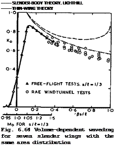
Experimental results have been provided by T E В Bateman & A В Haines (1961), and other workers already mentioned above. We reproduce here the results of tests on seven different delta wings in Fig. 6.64, which all have the same cross-sectional area distribution (that of wing 5 of W T Lord & G G Brebner (1959)) but different values of s/l and of the overall volume, following an analysis by J Weber (1976). In spite of some scatter, these results clearly

LIVE GRAPH
Click here to view
confirm that the general theoretical trends are realistic. The theory can indeed be used to design wings with Kq-values well below unity. Thus the estimates made in section 6.2 are not over-optimistic and should be attainable. The tests also indicate that Kg is a useful parameter for correlating results obtained for different wings. Fig. 6.64 includes results from tests on free-flight models by C Kell (1958) so that we can see what really happens at and near sonic speed. Both slender-body and thin-wing theories break down there, predicting an infinite drag at Mg = 1 , whereas the actual drag approaches the theoretical values from below when 8s/& exceeds about 0.2.
In this case the actual Kg-values never reach unity; they begin to climb steadily above the critical Mach number of about 0.95 and reach a maximum value near about 6s/I =0.1 , as would be expected physically. The results also indicate that the sonic area rule is quite inadequate for slender wings: the drag of the equivalent body of revolution (the first term in (6.59)) gives a value of Kg of about unity in this case, with a corresponding value of
2.1 for Kg in the case of the Newby area distribution given by (6.64).
Neither of these values has any physical meaning.


