NUMERICAL EXAMPLE
Computations of the stability and performance were carried out with (11.5,12) for the same jet transport airplane used in preceding examples, flying at sea level. The drag polar is (11.5,6) corresponding to the landing configuration. The data that differ from those of Sec. 9.1 are as follows:
CDx = .959, t* = .0460 sec, fi = 101.8,
Ve = 167.4 fps, CWt = 1.8, CDe = .377
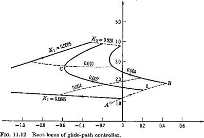
The eigenvalues corresponding to a range of Kx and K2 are shown on Fig. 11.12 in the form of root loci. Point A corresponds to the uncontrolled phugoid, and increasing proportional gain K1 with zero rate gain produces the branch A В of the locus. The system rapidly goes unstable without error-rate control, but is easily stabilized with a modest value of K2. For example, at point C on Fig. 11.12, with Kr = .002 (about 12° elevator per 100 ft of height error) and K2 = .010 (about 12° elevator per 20 ft/sec height error-rate), the eigenvalue characteristics are:
Phugoid: period = 10.4 sec ^=.54
Three real roots: th< = 94.0, 1.68, 0.86 sec

|
(а)
|
со m Fig. 11.13 (Contd.) |
The short-period mode has disappeared, being replaced by a pair of real roots, and the third real root is associated with the extra degree of freedom.
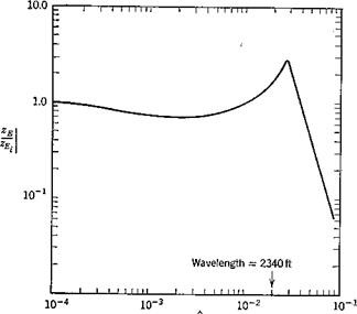
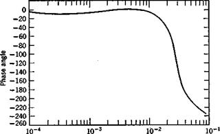
The performance of the system, i. e. its ability to track the glide slope, can be in part inferred from the frequency response associated with zEi input and zE output. This is computed by taking the Laplace transform of (11.5,12) (which simply changes D to s wherever it occurs), replacing s by id), and solving the resulting complex algebraic equations for the ratio zEjzE. as a function of a). The result is shown on Fig. 11.13. The system is seen to be able to follow waves in the ILS beam fairly closely down to wavelengths of the order of v,- mile (со = 2 X 10~2) at which point a phase lag of 40° has developed. This calculation is not, of course, sufficient to decide on the acceptability of the chosen gains. For that purpose one should calculate actual flight paths in the presence of wind shear and turbulence, and relate the dispersions to what is acceptable for a given mission.


