Shroud Design
The shroud controls the velocity and pressure at the rotor. It also permits a finite loading to be maintained at the tips of the rotor blades. The flow as it approaches the shroud is either accelerated or decelerated, depending on the application of the propulsor. In a low-speed, high-static-thrust application the flow is accelerated.
Consider first the behavior of the shroud without a rotor. Its effect on the flow can be separated into two parts—one due to camber, the other to convergence angle. The straight-sided duct shown in Fig. 9-3a has positive, zero, and negative convergence. Because the velocities and static pressures far ahead of and behind the duct must be equal, it is obvious that positive convergence diffuses the flow in the duct. In Fig. 9-3b positive camber is seen to have the same effect as positive convergence.
A diffusing shroud generating a circulation around its section is shown in Fig. 9-4. In this case the flow ahead of the shroud is given a radially outward induced component, whereas behind the shroud the flow is deflected inward. In an accelerating shroud the circulation and induced velocities are in the opposite direction.
 |
A solution of the aerodynamics of the shroud, or ring airfoil, comparable to thin airfoil theory, can be obtained by replacing the mean camber line of the airfoil by a continuous distribution of vortex rings. However, the
 |
analytical details of carrying out this procedure is complex and in general leads to a solution that is not of closed form. Provided that the configuration is not too extreme with regard to camber, it is possible to estimate the thrust on the shroud relatively easily by the application of a simple artifice.
This is done by replacing the shroud with a ring vortex located at its one – quarter chord line and satisfying boundary conditions at the three-quarter chord line. This approximation is referred to as Weissinger’s approximation and was mentioned earlier in Chapter 3.
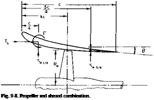
A ring airfoil is shown in Fig. 9-5. The convergence angle of the chord line is assumed to be small so that the axial distance between the quarter – and three-quarter chord points is approximately c/2. Tabulated functions, given in Ref. 2, relate Г, vh and the geometry of the ring. According to the
reference, the velocity induced at the three-quarter chord point can be expressed as
 |
(9-10)
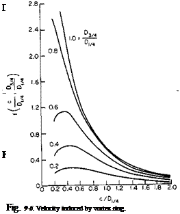
The function
is taken directly from Ref. 2 and is presented in Fig. 9-6; Г must be such as to induce a v( that, when added to the free-stream velocity and the velocity induced by the rotor, will produce a velocity tangent to the mean camber line of the shroud at the three-quarter chord location.
Radial Velocity Induced by the Rotor
The radial velocity induced by the rotor can be found approximately from the shape of the streamtube passing through an open propeller. If the rotor were producing a thrust of TR as an open propeller, then, from Chapter 4, the axially induced velocity varies with axial distance according to (4-54):
 (9-11)
where Z is the axial distance downstream of the rotor and Rr is the rotor radius.
From continuity,
(V + wa)nR2 = constant = (F + w0)nRR.
The slope of the streamtube walls with axial distance can be found by differentiating this equation with respect to Z.
![]() dR R(dwJdZ) dZ ~ 2(V + wa)
dR R(dwJdZ) dZ ~ 2(V + wa)
The radial component of velocity induced outward by the rotor is given approximately by
 (9-13)
Hence a combination of (9-11), (9-12), and (9-13) produces
![]() „ = 1
„ = 1
2 (Z2 + Rr)312 ’
where, from Chapter 4,
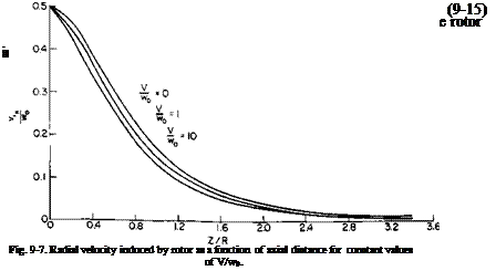
Equation (9-14) is presented graphically in Fig. 9-7.
Consider now the shroud and propeller combination in Fig. 9-8. According to Weissinger’s approximation, the resultant flow due to Г, the propeller, and the free-stream velocity should be tangent to the mean camber line at 3C/4:
V‘R3/4 V‘ _ 0
v + w-
or
vi = -«w – e(v + w«s/4);
but vt and Г are related through (9-10). Therefore
point, denoted as -%1/4. Hence the axial force on the ring vortex can be calculated from the Kutta-Joukowski law and the thrust on the shroud becomes
Ъ = ~pviRmTnDm
= Г*>(ДІ)і/4)2[-рца/4 – 0(V + и’Вз,4)]і)ІКІ/4
f(c/D, 4, D3/4/D1/4)
We now define a thrust coefficient for each component as
C – T
Ct~¥av2′
where A is the rotor disk area. Because ViR/F and wJV are functions only of the rotor thrust coefficient, it follows that the shroud thrust coefficient, hence the total thrust coefficient, is a function only of the rotor CT.
 |
To dwell further on this, consider the special case of a rotor in a straight duct. Here 0 = 0 and D3lJDm — 1.0.
In addition, let c/D = 1.0. Then, from Fig. 9-6,
and
Ts = U8p(nD)2viRi/4viRi/4 or
![]() де ViR 1/4 ViR3/4
де ViR 1/4 ViR3/4
V v ■
Using (9-14), we obtain
CT = 45 ^ i( -1 + J + CTR)2. (9-17)
Н’о щ
The product {viRyJw0) (viR14/w0) depends on the location of the rotor along the duct. From Fig. 9-7 the product has a maximum value of about 0.13
in this case with the propeller at c/2. It drops to 0.09 with the rotor at c/4 or 3c/4. Location of the rotor at c/2 gives
CTs = 1.46(71 + CTr – l)2. (9-18)
Notice that even though the duct is straight a thrust is developed on it
|
|
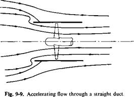
because of the action of the rotor. A more exact vortex treatment would show a singularity, hence a suction force at the leading edge of the duct. Because the shroud is developing a thrust, from the considerations leading to Eq. (9-9) the flow must be accelerating into the rotor, as shown in Fig. 9-9. This can also be deduced from the direction of Г.
|
|
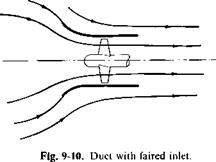
From Fig. 9-9 it is seen that the flow, in a real fluid, would probably separate on the inner side of the leading edge of the duct. To avoid this we curve the mean camber line out at the leading edge, as shown in Fig. 9-10. Theoretically, the thrust on the shroud would remain about the same. Practically, however, the cambered duct would come closer to the value given by (9-18), for separation in the straight duct destroys the leading-edge suction force. The shape for the camber can be calculated approximately from the streamline due to the ring vortex and the rotor acting as an open propeller. Observe, however, that the leading edge is tangent to the incoming flow only at one particular value of CTr.
In a shroud of finite thickness the inside appears to be the controlling surface in affecting the streamtube through the rotor. At least for the
|
|
о
HI
c
_o
CL
Flow
Axis of revolution
Fig. 9-11. Duct for which data of Fig. 9-12 were obtained (drawn to scale).
method presented here, better agreement is obtained with experiment if the inner surface of the duct rather than the mean camber line is used. To illustrate further, consider the performance of the duct shown in Fig. 9-11. This duct is taken from Ref. 3 which presents considerable test data on ducted marine propellers for different duct-propeller combinations. The pertinent geometry for the mean camber line and for the inner surface is tabulated in Table 9-1.
|
Mean Camber Line |
Inner Surface |
|
|
C/0,,4 |
0.455 |
0.486 |
|
Di/JDu* |
0.955 |
0.986 |
|
0 |
7° |
-2° |
|
Table 9-1 |
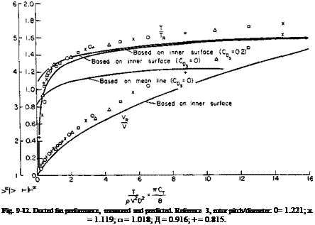 |
The rotor is located at midchord, and the distance from its rotor to c/4 or 3c/4 in terms of the rotor radius is 0.24.
In any comparison with experimental data the drag of the shroud must be considered. If cf is the drag coefficient of the shroud based on its wetted area, the decrement in the thrust coefficient based on A will be
or approximately
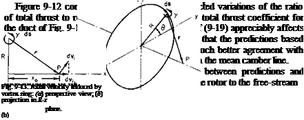 |
velocity. The velocity through the rotor is calculated as the sum of three components; the free-stream velocity V, the rotor-induced velocity w0, and the axial velocity induced at the rotor by the shroud. The axial velocity is assumed to be that induced along the centerline by the ring vortex located at the quarter-chord point. The latter component can be calculated by means of the Biot-Savart law. Consider the vortex ring shown in Fig. 9-13.
The Biot-Savart law states
у r x ds
From the geometry |ds| = RdO and r and ds are always normal to each other; also |r| is a constant. Further, the axial component of dv, is
dvia = |dv,| sin 0.
 |
|
Hence
Hence Vj is obtained from the above; the strength у is calculated from (9-15).


