Time-Averaged Effects on the Airframe
The effects of the generally nonsteady airloads averaged over many rotor revolutions are time-averaged effects. These can be considered as the effects that can affect the overall forces and moments on the airframe and, therefore, the flight characteristics of the helicopter as a whole. Wilson & Mineck (1975), Freeman & Mineck (1979), Sheridan & Smith (1979), Freeman & Wilson (1980), and Trept (1984) were among the first to conduct systematic tests to study the effects of the rotor wake on the time-averaged aerodynamic characteristics of helicopter fuselages. Considerable downloads and yawing moments induced by the rotor wake have been measured. The largest effects of the body on the rotor performance are in low-speed and hovering flight, and the body downloads are also the largest here. Subsequent experiments by other investigators [e. g., Smith & Betzina (1986), Liou et al. (1989a, b), Leishman & Bi (1990a)] have confirmed these basic findings.
 |
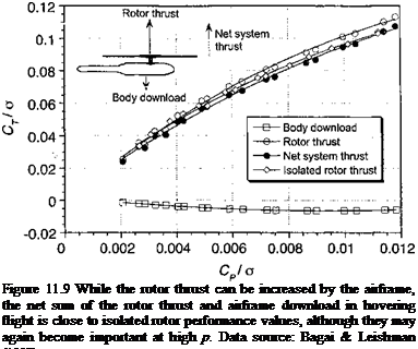
It is instructive first to examine in detail the net lifting performance of the rotor system (rotor plus body) in hovering flight. Representative results are shown in Fig. 11.9 as a function of rotor power required for the generic subscale model shown in Fig. 11.2. As previously discussed, with the body present the rotor thrust is increased relative to the thrust of the isolated rotor for a given collective pitch or power setting. The body also experiences a download that increases with increasing thrust, and hence the downwash velocity is increased below the rotor. In fact, the measured results simply confirm that the download on the body is proportional to /2 as might be expected based on the discussion in Section 6.6.2. It is apparent that the increase in thrust on the rotor is almost exactly equal and opposite to the download on the body, at least within the bounds of experimental accuracy. The net thrust of the system also agrees closely with the isolated rotor results, and while perhaps not an entirely unexpected result, it is not obvious that this should be the case.
|
pAQ2R2 |
|
Mf pAQ2R3 |
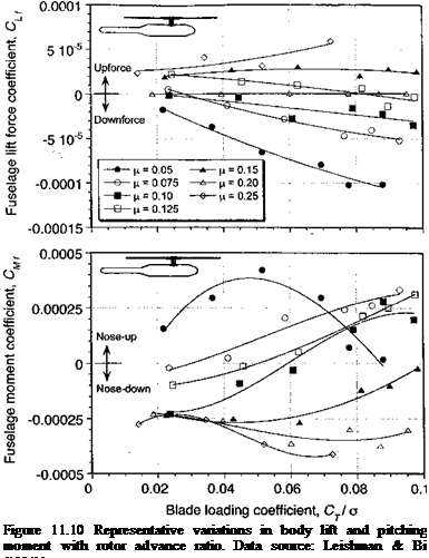
An example of the effects of the rotor on the lift and pitching moment of the body is shown in Fig. 11.10 for a range of rotor advance ratios up to д = 0.25; this would represent the range of д when transitioning from hover into forward flight or vice versa. Notice that the lift and pitching moment for the isolated body are close to zero for all advance ratios, so these results represent almost entirely the effects of the rotor on the integrated aerodynamics of the body. It should be noted that the results are plotted by nondimensionalizing the body forces and moments by using rotor tip speed, that is,
This is necessary because if standard coefficient values are used (based on free-stream velocity Vqo) the effect of increasing д will be to decrease the coefficient values for a constant lift and may produce misleading trends.
The results in Fig. 11.10 show that the rotor provides the most significant download on the body at low advance ratios. As the advance ratio is increased the download decreases,
 |
and an upforce is actually obtained at high advance ratios. Similar results have been obtained by Smith & Betzina (1986). The source of the upflow reflects the low pressure region produced on the upper part of the body because of the higher-speed flow in the rotor wake (see Fig. 11.7). The results in Fig. 11.10 also show that the fuselage pitching moment decreases (i. e., the moment changes from nose-up to nose-down) with increasing advance ratio. This is because the rotor wake modifies the pressure distribution on the body such that the net center of pressure moves further aft from increasing the advance ratio (see Figs. 11.11 and 11.12). Overall, the foregoing results reflect the significant changes in the pressure distribution on the body as the position of the rotor wake is changed by varying rotor thrust and the advance ratio.
We can examine in more detail the source of the pressure distribution found over the body surface. A pressure coefficient can be defined in terms of the rotor tip speed, QR, as
|
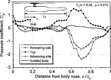
Figure 11.11 Static pressure distribution on top and sides of a body at fx = 0.075. Data source: Leishman & Bi (1994b). |
where the factor of 100 is simply a scaling. This form of coefficient was introduced by Liou et al. (1989a, b) and has become accepted by many investigators for the purposes of helicopter interactional aerodynamic studies because it gives an indication of the actual pressure on the body, so they can then be more readily compared at different advance ratios. Examples of the measured pressure distributions along the top and on the two sides of a body are shown in Fig. 11.11 for an advance ratio of 0.075. In general, the results show that the rotor wake has a pronounced effect on the body pressure distribution. A significant
|
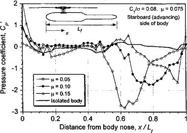
Figure 11.12 Static pressure distribution along the starboard side of a body as induced by the rotor at several rotor advance ratios. Data source: Leishman & Bi (1994b). |
increase in static pressure is obtained over the top of the body in regions affected by the rotor wake because the wake induces a relatively high dynamic pressure there. There are large suction pressure peaks on the sides of the body, and this is a direct consequence of the wake flow being accelerated over the sides of the fuselage.
As the advance ratio is increased the wake is skewed back (see Fig. 11.7), and the results in Fig. 11.12 show that the suction peaks produced by the rotor wake move aft along the body. It should be apparent that the high adverse pressure gradients downstream of the suction peaks will cause the boundary layer to be susceptible to flow separation. This is a good example, that shows why 3-D flow separation is inevitably always involved in helicopter airframe aerodynamics, and why the modeling of the flow over airframe surfaces will be relatively difficult (see also Section 14.7). Another aspect of the pressure distributions shown in Figs. 11.11 and 11.12 is that the distributions on the two sides of the rear fuselage are different, with a higher suction pressure obtained on the retreating (port) side of the tail boom. This indicates that because of the rotor wake the fuselage will experience both a side force (to port) and a yawing moment (nose-right) for a rotor rotating in the conventional (counterclockwise) direction. On an actual helicopter, this may be important from a handling qualities perspective, as pointed out by Wilson & Mineck (1975). Notice also that this side force is in a direction opposite to that required for anti-torque purposes, so a tail rotor will have to produce more thrust (and consume more power) to compensate. The integration of the tail rotor into the overall flow field, however, will further change the body airloads to some degree but there are few results available in this case that clearly delineate this effect.


