Trefftz-plane loads
An alternative to the above near-field force calculation is to use the far-field or Trefftz-plane approach. In general, this is a more reliable approach especially for the Di component, since it avoids the usual pressure- drag cancellation errors discussed in Chapter 5, these being especially problematic with the simple leading Vortex Lattice Method
The Vortex Lattice (VL) method is a numerical solution implementation of the general 3D lifting surface problem described above. It is also the simplest general 3D potential flow calculation method. It is commonly used in initial aircraft configuration development, where its simplicity and speed allow a large number of configurations to be examined. It is also used for initial structural load estimation, and to provide the trim state values and stability and control derivatives for the linearized force and moment equations (6.12), (6.13).
6.5.1 Vortex lattice discretization
 |
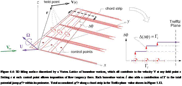
The VL method discretizes the vortex-sheet strength distribution on each lifting surface and its wake by lumping it into a collection of horseshoe vortices, as shown in Figure 6.6. Each horseshoe vortex (h. v.) consists of three straight legs, or segments: a bound leg which lies on the surface, and two trailing legs extending from the bound leg’s endpoints to downstream infinity and parallel to the x axis. All three legs of the i’th h. v. have the same constant circulation strength Г.
In a discrete sense, this configuration of vortices satisfies the zero-divergence requirement on the vortex sheet strength y(s, e) which is discussed in Section 2.4, since any circuit drawn on the surface will have a filament with a fixed circulation both entering and leaving it. Note also that each h. v. adds zero net circulation in the Trefftz plane, where its two trailing legs have equal and opposite circulations.
An equivalent interpretation of the h. v. configuration is a piecewise-constant potential jump or normal – doublet distribution. Each h. v. contributes Д(д^>) = Г to the total potential jump д^> within its perimeter. The total circulation of all the h. v.’s in a chord strip then gives the д^> in the Trefftz plane, as shown in Figure 6.6. This д^> is also shown in Figure 5.12, where it’s used to construct the Trefftz-plane velocity and evaluate the Trefftz-plane forces.


