Unsteady Rotor-Fuselage Interactions
Considerable attention has been placed on the measurement and prediction of the unsteady pressures induced on a fuselage below a rotor. In many cases, the unsteady pressure fluctuations are much larger than the mean pressures. All parts of the fuselage surface are subjected to unsteady loading, both in magnitude and phase. Because the distribution of pressures is very complicated in nature and has contributions from multiple sources (rotor, individual blades, wake, etc.), it has proved difficult to isolate or characterize unsteady pressure responses and correlate the behavior with specific physical phenomena. As previously mentioned, the isolation of phenomena is very necessary for the validation of mathematical models, such as those for wake distortion and tip vortex impingement on the airframe – see Section 11.2.5.
Liou et al. (1989a, b) and Brand et al. (1989,1990) have conducted experiments to investigate the aerodynamic interactions between a cylindrical body and a rotor. Measurements of the instantaneous and time-averaged pressures on the cylinder surface were obtained. Measurements of three velocity components of the flow at selected regions were also made using LDV techniques. Leishman & Bi (1994a, b) have made similar measurements using the configuration shown in Fig. 11.2. In both experiments, flow visualization of the trajectories of the wake vortices complemented the measurements. All of these results have helped to provide a reasonably comprehensive picture of the underlying interactional flow mechanisms, while also providing an extensive data base for validation of predictive models (see Section 11.2.5).
Based on the various experimental studies that have been performed, it is apparent that the unsteady airloads on the airframe that are associated with the presence of the rotor and its vortical wake can be classified into four distinct types. These are: 1. blade passage effects, 2.
|
1 o. o-rf^4 О |
![]()
 |
0.0 90.0 180.0 270.0 360.0 0.0
Blade azimuth position (time), – deg.
Figure 11.13 Characterization of unsteady pressure signatures on an airframe below a rotor, (a) Blade passage, (b) Close wake-surface impingement, (c) Wake-surface impingement. (d) Post wake-surface impingement. Data source: Bi & Leis’nman (1990), Leisnman & Bi (1994b).
close wake-surface interactions, 3. wake-surface impingement, and 4. post wake-surface impingement.
Type-1 Interactions: Blade Passage Effects
Blade passage effects have been measured and reported by Bramwell (1966), Brand et al. (1989), Leishman & Bi (1990), and many other investigators. More recently, Le Pape et al. (2004) have measured surface pressure loads on a geometrically scaled helicopter fuselage model that were induced by blade passage. An example of the unsteady pressure response measured at a location directly under the rotor is shown in Fig. 11.13(a). The results show that large pulses are produced that are exactly in-phase with the blade passage over the body (i. e., for a four-bladed rotor they occur at jf = 0°, 90°, 180°, and 270°). This type of signature has been noted to be relatively independent of advance ratio so it must be associated with the local loading on the rotor itself; in other words, the main features of this type of signature are not coupled to the strength of the rotor wake or the rotor wake geometry. Therefore, it is called a blade passage effect and is classified as a Type-1 interaction.
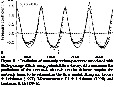
The blade passage effect can be examined from a parsimonious potential flow analysis of a series of line vortices moving at velocity rQR (r = y/R) at a distance h above a surface. A simple model such as this is given by Bramwell (1966) with later extensions by Lorber & Egolf (1990) and Crouse et al. (1992). The vortex represents the bound circulation at some
point on the blade at a radial distance у from the hub. The surface plane representing the body is made into a streamline of the flow using an image system. If the circulation along the blade is assumed to be uniform (a good assumption for a rotor with twisted blades operating in hover), then the circulation Г can be related to the blade loading using Eq. 3.111. With these assumptions, along with Kelvin’s equation for the velocity potential, it can be shown that the pressure coefficient at some point x on the surface is given as a function of blade azimuth, xj/, by
(П. З)
The first term in Eq. 11.3 is a steady or quasi-steady contribution to the pressure and the second term is the unsteady contribution. Results using Eq. 11.3 are shown in Fig. 11.14 where the pressure signature is found to be in excellent quantitative agreement with the measurements. The unsteady term clearly dominates the quasi-steady term. This immediately illustrates the necessity of retaining the time-dependent terms in any type of predictive aerodynamic model, if the rotor-body interaction airloads are to be properly predicted.
 |
The significance of the unsteady terms is further appreciated when the model is compared with the experimental data measured on the fuselage directly under the rotor disk.
Blade azimuth position (time), г|> – deg.
Distance from rotational axis, у / R
 |
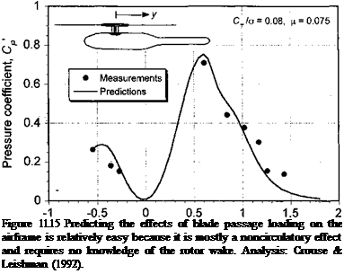
According to the model described by Eq. 11.3 the approximate magnitude of the unsteady pressures on the body resulting from the blade passage should be: 1. Proportional to the rotor disk loading (which is proportional to CTJo for a given rotor and tip speed), 2. Inversely proportional to the distance of the rotor blades above the measurement point (i. e., the rotor-body spacing), and 3. Proportional to the speed of the blade past the measurement point (i. e., rotor tip speed and distance along the blade). This parsimonious model confirms what is already known from numerous experimental studies, that the unsteady loads induced by blade passage effects will become much more pronounced on rotorcraft with higher disk loadings and smaller rotor-airframe spacing. Recall that the airframe loading in this case can be considered as a noncirculatory effect because it depends only on the blade loading and requires no explicit knowledge of the circulation that is shed or trailed into the rotor wake.
Figure 11.15 shows a comparison of the peak-to-peak values of the unsteady pressure at two points directly below the rotor as a function of rotor thrust. It can be seen that the agreement between theory (see also Section 11.2.5) and experiment is indeed very good. The blade passage effect is found to be largely independent of rotor advance ratio. This behavior is to be expected because any changes in either advance ratio or TPP angle will only slightly affect the longitudinal variation of lift over the rotor (i. e., the distribution of circulation on the rotor blades as they pass above the body). These results confirm the validity of more general potential flow approaches for rotor-airframe aerodynamics, such as those of Lorber & Egolf (1990), Crouse & Leishman (1992), and Waschpress et al.
(2003) .


