Wake Developments in Maneuvering Flight
The problem of modeling helicopter rotor wakes under maneuvering flight conditions is not a new one [see Sadler (1972)]. The effects on the inflow resulting from rotor wake distortion during maneuvering flight has been suggested as one of the contributing sources of the so-called “off-axis” response problem of helicopters. This problem manifests as a pitch response resulting from a lateral cyclic input and/or a roll response resulting from a longitudinal cyclic input in pitch – see, for example, Tischler et al. (1994), Mansur & Tischler (1996), and Keller & Curtiss (1996). A maneuver, whether it be pitching or rolling or a combination of such, clearly provides an additional potential source of aerodynamic forcing into the rotor problem and would be expected to produce some further distortion effects into the rotor wake compared to that obtained under straight-and-level flight conditions. The exact understanding of how this effect occurs, however, is the subject of ongoing research. Clearly, if a modified wake topology is produced by the maneuver, this will change the induced inflow, which in turn will affect the blade loads, the rotor flapping response, and, therefore, the control inputs required to execute the maneuver. The problem is how to calculate such highly coupled effects, which requires a fully integrated aerodynamic, rotor dynamic, and flight mechanics simulation. While comprehensive flight mechanics models are available, the fidelity of the aerodynamic models that can be viably included so far has been limited because of their extremely high computational costs.
There have been several recent developments of rotor wake models directed toward the understanding and prediction of the off-axis response problem. Basically, this is a nonin- tuitive flapping response of the rotor resulting from the maneuver. For example, for a roll to the right (to starboard) then conventional theory (i. e., linearized, blade element theory) would say that the change in velocity across the disk from a roll rate would increase the AoA and lift of the blades on the advancing side of the disk and decrease the lift on the retreating side. This would be expected to cause a backward flapping of the rotor disk, that is, a —fic flapping motion. Instead, in practice the rotor disk is found to flap forward and this is one consequence of the off-axis response problem. Using a relatively simple
prescribed wake with assumed (prescribed) maneuver induced distortion effects, Rosen & Isser (1995), Arnold etal. (1995), Keller & Curtiss (1996), and Barocela et al. (1997) showed improved correlations of the off-axis rotor response when compared to flight test data. Rosen & Isser’s approach, like most vortex wake models that may have the fidelity necessary to predict maneuver induced wake distortion effects, is computationally expensive to include in flight mechanics simulations. The techniques of Keller & Curtiss (1996) are based on an extended momentum theory approach to represent the effects of the rotor wake, and is in a form easily included in such simulations. Both these techniques, however, assume that the maneuver-effects on wake distortion can be preassumed. This is done by correlating
tbp r^cnltc x/itb fiiaht fpct Ante* япН inpliiHintr foptnre infn tbp чх/яЪ-а гппНрі tViat пглНпрр tbp
U1V Д WLFM1I. LJ ТТДИІ I. VU *. UUVU U11V* IXIVlUUiUg 1UVIVJLO 4444ЧУ V11V TT ULW lllV/4iVl U1UI j^/IVUUW VliW
desired response. While these empirical approaches can give good results, they give limited insight into the understanding of the underlying aerodynamic mechanisms that may contribute to the off-axis response problem.
Bagai et al. (1999) have approached the aerodynamic aspects of the problem using free – vortex wake simulations. The effect of maneuvers on the rotor wake developments and induced velocity field can be simulated by adding additional “source” terms to the right – hand side of the governing equations of the wake. For example, the source term in Eq. 10.54 can be represented, in general, as
![]() ^loc(^"(V9>> VAi)) — Voo T" Vind T Vman,
^loc(^"(V9>> VAi)) — Voo T" Vind T Vman,
where Vqo is the external velocity field, Vjn(i is the velocity field induced by the rotor blades and their respective wake vortices from both steady and unsteady aerodynamic effects, and the Vman term is the additional maneuver-induced velocity perturbation, which will be a
![]()
 і/all oc tbp rvAOitiAnc /"vf tbp urobp filomantc гріotitra trv ‘V VU (40 411V/ ^WOltlVllO VI 411V/ W C4JVV – 111CU11V/1140 1. V/1C441 V V/ IV
the maneuver axis. For simple pitching and rolling motions about the rotor hub axes, the maneuver rate vector can be written as pi +qj + rk, where it is assumed that the rotor rolls about the fixed x axis and pitches about the fixed у axis. Furthermore, because the position of a vortex element in the Cartesian coordinate system is defined by three spatial locations, its position vector can be represented as r{fr, £) = xi + yj + zk. The cross-product of the two vectors defines the additional maneuvering velocity field encountered by the free vortex filaments in the wake, which is
![]() О = ~(qz – ry)i + (pz – rx)] + (qx – py)k.
О = ~(qz – ry)i + (pz – rx)] + (qx – py)k.
The first term in Eq. 10.127, which is the x or streamwise component of the velocity resulting from a pitch-rate q and/or a yaw-rate r, essentially produces a skewing distortion of the wake. The second term, which is the у or lateral component of the velocity resulting from a roll-rate p and/or a yaw rate r, produces a skewing in the lateral direction. The third {ax — py) term in Eq. 10.127, results in an asymmetric axial stretching distortion of the wake, which appears like a wake curvature.
In addition to the aerodynamic effects, there are inertial effects on the blade motion during maneuvers. The rotor TPP lags behind the shaft or control plane by a finite angle – see Fig. 6.32. The additional flapping moment on the blades resulting from gyroscopic effects on a rotor with pitch rate q and roll rate p is
Mg = —2 Ib^lq sin ]/ — 21ъ$1р cos + Qq cos fs + Q p sin fr, (10.128)
which must be added to the equation of motion for a flapping blade (Eq. 4.5).
……. Hover (reference)
 |
z A ——– Maneuver, pitch rate q= q/Q = 0.024
1.5
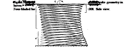
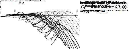
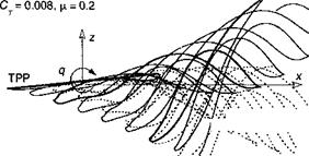
Examples of predicted free-vortex wake geometries under idealized (nose-up, positive) pitch rate conditions are shown in Figs. 10.50 and 10.51, for hover and forward flight, respectively. The imposed angular rates are relatively high for a helicopter, but they have been selected to exaggerate the basic effects obtained on the wake geometry. Notice the general characteristics manifest as a curvature-type distortion and an axial-tvpe distortion. These are physical effects that have been labeled by Keller & Curtiss (1996) as “bending” and “stretching” of the wake, respectively. Furthermore, notice that for a positive (nose-up) pitch rate, the vortex elements (tip vortices) at the front of the rotor are further way from the TPP compared to straight-and-level flight conditions. At the back of the disk, the tip vortices are much closer to the TPP. In many ways, these maneuver-induced effects on the wake distortion are similar to an increase in skewness of the wake relative to the rotor TPP. Therefore, the resulting wake distortion must manifest as a change in the longitudinal inflow distribution, which will be expected to be more biased toward the back of the disk.
Consider now a simulated piloted maneuver, such as a roll. In an actual roll maneuver the pilot banks the helicopter in one direction by applying appropriate cyclic control inputs and maintains altitude by using collective pitch. The roll rates imposed on the helicopter can be approximately described using a linearized equation for roll motion – see Padfield
(1996) . The governing equation for the roll dynamics (with the usual simplifications) can be written as
![]() P 1-ipP — r^latOiat
P 1-ipP — r^latOiat
where Lp and Ь$ы are stability and control derivatives (in roll). The solution to Eq. 10.129 for a step input of lateral cyclic, <$iat, is given by
![]() (10.130)
(10.130)
The resulting bank angle is
 (10.131)
 |
 |
The roll trajectory can, therefore, be simulated by setting parameters such as the desired maximum roll rate and the maximum bank angle. The control inputs for the maneuvers can be generated by imposing a step input, which is then held fixed for a given duration. In this case, the asymptotic value of Eq. 10.131 is given by
Ad> = At. (10.132)
Lp –
Defining the time period over which the maneuver is performed allows the bank angle of the simulation to be determined using Eq. 10.131.
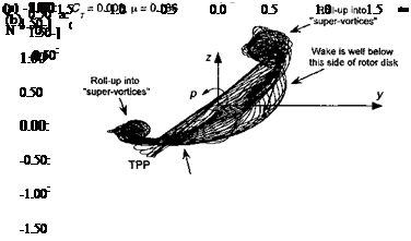
Figure 10.52 shows an example of the wake behind a rotor executing a simulated starboard and port roll maneuver. The roll to starboard delays the roll up of the wake vortices from the advancing side of the rotor disk. However, the maneuver also brings the blade tip vortices closer to the rotor at the back of the disk thereby enhancing the potential of В Vis there. The wake behavior for a port roll is similar, except that now the wake passes up more through the retreating side of the rotor disk. The port roll maneuver also causes a lag in the roll up
 |
y/R
Figure 10.52 Rear views of representative predicted wake geometries for a rotor undergoing a roll maneuvers, CT = 0.008, ju, = 0.186, у = —6°. (a) Starboard roll rate; (b) Port roll rate. From Ananthan & Leishman (2004).
of the wake on the retreating side of the rotor because of the change in airloads over the disk. The rolled-up bundle of tip vortices trailed from the disk also move more inboard on the rotor disk and below the rotor TPP. The wake roll up on the advancing side seems to intensify during a port roll maneuver, which causes strong BVIs and high impulsive loads over the first quadrant of the rotor disk throughout the entire maneuver.
Theodore & Celi (1998) and Ribera & Celi (2004) have incorporated dynamic inflow as well as relaxation and time-accurate free-vortex wake models into a flight mechanics simulation for the analysis of such maneuver problems. The results showed some improvements in predicting overall trends in the free-flight response of the helicopter to cyclic inputs, but the quantitative predictions of rotor response were only marginally improved. The use of time-accurate aerodynamic modeling is clearly an enhanced approach, yet the results from this study suggest that deficiencies are still present in the aerodynamic models. There may be other mechanisms that play a role in predicting rotor airloads during maneuvers and so in eventually resolving the off-axis response problem, and the issues are still the subject of ongoing basic research.
10.12 Chapter Review
This chapter has described some of the significant problems still associated with an improved understanding of the wakes generated by helicopter rotors. The proper modeling of the rotor wake is one key to the prediction or rotor airloads and rotor performance. Problems such as tip vortex formation, blade-vortex interaction, and rotor-airframe interference are better understood, and systematic experimental measurements have provided significant results that will help validate numerical predictions of the various phenomena. Recent advances in experimental techniques for flow visualization and 3-D velocity field measurements have been significant, and further developments will likely continue. Ambitious experimental tests with rotors have generated large amounts of important results that have provided new insight into old problems and remarkable insight into other problems that were previously considered intractable. However, the complexity of the helicopter rotor wake, together with the sensitivity of its topology to the flight condition, makes all types of rotor wake experiments time consuming and expensive to undertake. The challenge to the rotor analysts of the future is to balance needs with experimental capabilities and to use complementary flow diagnostic techniques wherever possible to provide an improved understanding of the various rotor wake-related phenomena.
One of the biggest challenges still remaining in helicopter rotor analysis is to reveal more completely the intricate structure of the blade tip vortices. This includes issues such as the vortex strengths, the viscous core size, and velocity field near to and inside the core, as well as their relationships to the loading on the blades. Fundamental issues such as diffusion and core growth of the vortices are not yet fully understood, and further work still needs to be undertaken to develop more general models. These models must include vortex Reynolds number effects. This diffusive behavior is compounded by interactions of vortices and blades, which causes filament stretching. Such problems cannot yet be examined using computational methods based on first principles and require careful experimental studies with rotors in both hover and forward flight. This type of research may result in new ideas for tip vortex control and possibly the alleviation of several of the complex problems involving vortex dynamics that hinder the development of quieter helicopters with better performance and lower vibration.
The long-term goal of the aerodynamic modeling efforts is to be able to predict the flow field around the entire helicopter when operating in any flight condition, including flight near the ground and during arbitrary flight maneuvers. To this end, the prediction of the rotor wake is fundamental to solving the problem. However, increasing emphasis is also being placed on rotor-airframe interaction problems (see Chapter 11) because of their importance in determining performance, vibration levels, and also the overall handling qualities of the helicopter. Rapid advances in computer power mean that prescribed vortex wake models are rapidly giving way to free-vortex models for many routine levels of helicopter analysis and design work. Dynamic inflow represents another formulation of the problem, where the effects of the wake can be included in a form of differential equations to represent the relationship between the time-dependent inflow velocities and the rotor forces and pitching moments. This latter approach is attractive for some problems in rotor analysis, particularly those in flight dynamics and aeroelasticity. All of the existing rotor wake methods are relatively powerful and can give good results, yet caution should be used. Quantitative errors can only be determined though correlation studies with experiments, and much further validation of wake models is required, particularly in improving the confidence in predicting the combined effects of the rotor flow and the airframe. These problems are discussed next in Chapter 11.


