14.2.1 The Boundary Layer Concept
The concept of a boundary layer can be described by considering the flow past a two-dimensional flat plate submerged in a uniform stream, as shown in Fig.
14.5. Since the viscous-flow boundary conditions on the solid surface (Eqs.
FIGURE 14.5
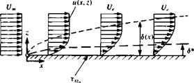 Nomenclature used to describe the boundary layer on a flat plate at
zero incidence.
(1.28a and b)) require that the velocity be zero there, a thin layer exists where the velocity parallel to the plate reaches the outer velocity value Ue (Ue is the velocity outside of the boundary layer and in the case of the flat plate of Fig.
14.5 Ue = 14). This layer of rapid change in the tangential velocity is called the boundary layer and its thickness d increases with the distance x along the plate. The information about the velocity profiles inside the boundary layer can be obtained by solving the inner viscous flow problem (e. g., see Ref. 1.6) and from the outer potential-flow point of view the boundary condition of zero normal velocity can be moved from the plate to an imaginary distance 5* (see Fig. 14.5) that is called the displacement thickness. If the velocity distribution within the boundary layer is known (from a solution of the boundary layer equations) then <5 * can be calculated as
![]()
 (14.3)
This displacement thickness is described schematically in Fig. 14.6 and it indicates the extent to which the surface would have to be displaced in order to be left with the same flow rate of the viscous flow, but with an inviscid velocity
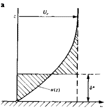 FIGURE 14.6
Illustration of the displacement thickness d* in a boundary layer. (Note that the area enclosed by the two shaded triangular surfaces should be equal.)
 |
profile (of m(z) = Ue = const.). Consequently, the boundary of the surface for the potential-flow boundary conditions must be raised by 6*, as shown in Fig.
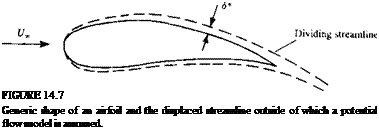
14.5. For a more complicated geometry, such as the airfoil shown in Fig. 14.7, the displaced streamline defines a modified geometry for the potential-flow solution that accounts for this displacement effect. A possible procedure for solving the coupled potential and boundary layer equations can be established as follows:
1. Solve the potential flow field over the body and obtain the surface pressure distribution.
2. Using this pressure distribution obtain the boundary layer solution of Eqs. (1.64) and (1.65).
3. Modify the surface boundary condition for the potential flow (e. g., specify it on the displacement surface between the viscous/inviscid regions, as in Fig. 14.7) and solve for the second iteration.
This iterative process can be repeated several times and there are some different approaches for modifying the potential-flow boundary conditions.
 |
|
One approach (e. g., Refs 9.5 and 14.3) is to change the location of the dividing streamline (or the boundary) in order to account for the displacement thickness. The other approach (which was presented in Section 9.9) is not to change the geometry of the surface but to simulate the displacement by blowing normal to the surface (e. g. Refs. 12.11, or 14.4-14.7). This requires the modification of the boundary condition of Eq. (9.4) such that
|
d(Ue6*) ds |
and then the transpiration (or blowing) velocity V„ is found from the information provided by the boundary layer solution:
where s is the line along the surface and the minus sign is a result of n pointing
into the body. In the case of the Dirichlet boundary condition the source term of Eq. (9.12) (e. g., in the panel code VSAERO9 2,12 n) can be modified such that
![]() W)
W)
ds
This approach is based on the two-dimensional boundary layer model and when extended to three-dimensional flows, in practice, it is done along streamlines or along two-dimensional sections.
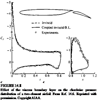
Based on such an iterative coupling between the inviscid and viscous solutions, the effect of the displacement thickness is presented in Fig. 14.8 for a two-element airfoil (shown in the inset). For the attached-flow case, the presence of the thin boundary layer reduces slightly the pressure difference (and hence the lift) obtained by the inviscid solution. This effect increases with the airfoil’s angle of attack (see lift coefficient data in Fig. 14.9) as the upper boundary layer becomes thicker, and eventually flow separation is initiated near the trailing edge (for a approximately larger than 5°, in Fig. 14.9).
 |
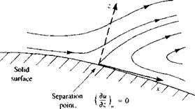
When the flow separates the streamlines do not follow the surface of the body, as shown schematically in Fig. 14.10. This is the result of an adverse (positive) pressure gradient (which may be caused by high surface curvature), which slows down the fluid inside the boundary layer to a point where the normal velocity gradient at the wall becomes zero. For laminar flows,
 (14.7)
and behind this point reversed flow exists.
Additional information from the boundary layer solution includes the estimation of the skin friction on the solid boundary. Since the viscosity reduces the tangential velocity component to zero on the surface, as shown schematically in Fig. 14.5, there is a shear force xxz acting on the solid surface. Now, recall Eq. (1.12) for the shear force xXZw near the wall (assuming constant
 |
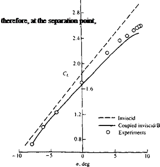 |
FIGURE 14.10
Flow in the boundary layer near the point of separation.
viscosity and laminar flow)
![]()
![]() (14.9)
(14.9)
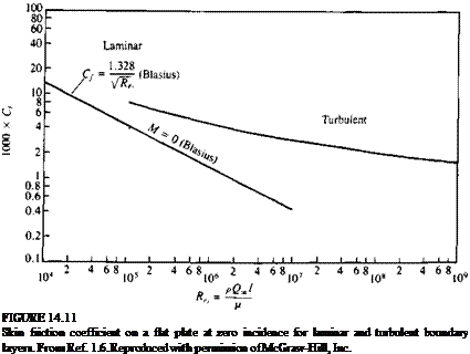
So, in principle, if the boundary layer equations are solved, the local friction on the surface can be readily obtained from the velocity gradient near the wall. Also, the skin friction coefficient strongly depends on the Reynolds number, and typical results for the flow over a flat plate are presented in Fig. 14.11. Of course our discussion has been limited so far to steady laminar flow and the skin friction coefficient for this laminar case is given by the line on the left side of Fig. 14.11. However, due to disturbances in the free stream or those generated in the viscous shear layers near the surface (e. g., due to surface roughness), the flow may become “turbulent” and the velocity will have time-dependent fluctuations. For example, in the case of a turbulent boundary layer over the two-dimensional flat plate of Fig. 14.5, the velocity m(z) at a given x location becomes time-dependent and will have the form

 |
u(z, t) = u(z) + u’(z, t)
Similarly, the normal velocity component is
![]() w(z, t) = w(z) + w'(z, t)
w(z, t) = w(z) + w'(z, t)
where m(z) and w(z) are the mean velocity components, and u'(z, t), w'(z, t) are the time dependent fluctuating parts. So, in principle, in an undisturbed flow, initially the boundary layer is laminar, as shown in Fig. 14.12, but as the distance x and the Reynolds number increase, the flow becomes turbulent. The region where this change takes place is called the region of transition.
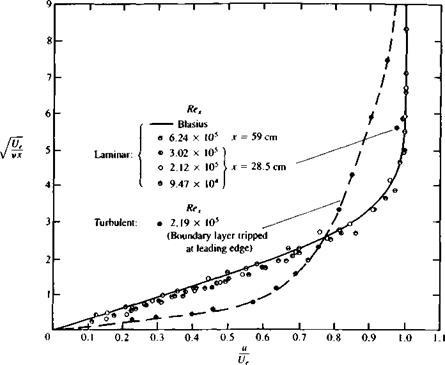
Figure 14.12 schematically indicates that due to the fluctuating velocity component (larger momentum transfer) the turbulent boundary layer is thicker. The typical boundary layer velocity profiles of Fig. 14.13 for turbulent and laminar flow reinforce this, too. Furthermore, when examining the turbulent boundary layer equations, the shear force becomes (Schlichting,1 6 p. 562)

 |
(14.11)
and the second term is the Reynolds stress and represents additional stress due to axial momentum transfer in the vertical direction. A closer observation of the two velocity profiles of Fig. 14.13 shows that the velocity gradient for the turbulent case (duldz) appears to be larger near the wall. Now we can examine Fig. 14.11 again and it is clear that the skin friction coefficient for the turbulent boundary layer is considerably larger than for the laminar boundary layer at the same Reynolds number. So before proceeding to the next section, we can conclude that:
1. Displacement thickness is larger for turbulent than for laminar boundary layers.
2. The skin friction coefficient becomes smaller with increased Reynolds number (mainly for laminar flow, see Fig. 14.11).
3. At a certain Reynolds number range (transition) both laminar and turbulent boundary layers are possible. The nature of the actual boundary
|
FIGURE 14.13 Velocity profiles on a flat plate at zero incidence for laminar and turbulent boundary layers. From Dhawan, S., “Direct Measurements of Skin Friction”, NACA Report 1121, 1953. |
layer for a particular case depends on flow disturbances, surface roughness, etc.
4. The skin friction coefficient is considerably larger for the turbulent boundary layer.
5. Because of the vertical momentum transfer in the case of the turbulent boundary layer, flow separations will be delayed somewhat, compared to the laminar boundary layer (see Ref. 14.8, p. 415).


