
Our heavyweight helicopter equal in the world does not have
In Rostov started production of the most load-lifting rotary-wing car The Russian holding «Helicopt[...]

Everything about aircrafts and helicopters. News and events in aviation worldwide. Civil, transportation, military helicopters and airplanes.

Everything about aircrafts and helicopters. News and events in aviation worldwide. Civil, transportation, military helicopters and airplanes.

Everything about aircrafts and helicopters. News and events in aviation worldwide. Civil, transportation, military helicopters and airplanes.

Everything about aircrafts and helicopters. News and events in aviation worldwide. Civil, transportation, military helicopters and airplanes.


The general formulation of the flow problem for a wing in close proximity to the ground, presented in section 2, covers a wide range of aerodynamic modes of the operation of ground-effect machines for h <C 1.
In what follows, attention will be attached to the particular case of a flying wing with endplates in the extreme ground effect, when relative gaps under the tips of the endplates are small.
In this case, the leakage of air from under the lifting surface is hampered, resulting in a considerable improvement in performance. Whereas for h —> 0, the description of the flow under the wing is independent of the vertical coordinate (see section 2), for vanishing gaps between the endplates and the ground, the channel flow becomes almost one-dimensional. Accounting for the fact that the upper flow contribution can be shown to be of the order of 0(/i), one can conclude that for a lifting system in the extreme ground effect and small clearances under the tips of the endplates, the dominant nature of the flow is one-dimensional.
A simple one-dimensional model of channel flow with leakage was first introduced by Gallington et al. and will be called the G-theory herein. It was assumed therein that the flow parameters are independent of the chordwise coordinate and that the leaking flow escapes into the external region of atmospheric pressure. To account for the intensive generation of vortex sheets emanating from wing’s side edges, the G-theory implies that separation occurs at the tips of the endplates. Though simple, the G-theory of channel flow agrees qualitatively with experiments and provides useful similarity criteria, convenient from the viewpoint of processing test data and designing vehicles. As pointed out by Ando [62], Gallington’s flow model does not exhibit the infinite (logarithmic) increase of velocity at the gap encountered in other flow models. However, due to the assumption that the flow parameters (velocity, pressure) are not dependent on the chordwise coordinate, the G-theory cannot be used to predict the moments and characteristics of longitudinal stability. Secondly, the model under discussion does not account for edge effects, thus preventing determination of such characteristics as, for example, the suction force at the leading edge.
In what follows, an extended one-dimensional flow model is introduced for a wing with small gaps under the endplates; see Rozhdestvensky [63]. This new model accounts for chordwise variation of the channel flow velocity and incorporates unsteady effects. It can be used for evaluating the efficiency and stability of a simple flying wing configuration in the extreme ground effect. It also produces formulas, useful for processing of experimental data,
identification of parameters of the lifting system, and eventually, can serve as a tool of conceptual and preliminary design.
Below, follows a derivation of the governing equation for unsteady flow past a lifting surface with small gaps between the tips of the endplates and the ground.
|
/l*(x, 2, t) |
|
h*(x, z, t) |
We recall a general limiting problem, formulated earlier for the velocity potential of the absolute motion of a fluid when h —> 0; see paragraph 2.7. This problem is governed by the quasi-harmonic equation
which can be obtained from (2.115) by replacing the absolute potential ірг with the potential of relative motion ф and h* = h*/h0 with h* = h*(x, z,t). As previously, the latter quantity represents the local clearance under the wing. All functions and parameters are rendered nondimensional by using the root chord C0 and a characteristic velocity U0.
Restricting the analysis to a rectangular wing (see Fig. 4.7), we average equation (4.46) spanwise by using the integral operator
where Л is the aspect ratio of the wing.
Assume additionally that the clearance distribution function depends only on the longitudinal coordinate and time, i. e., h* = h*{x, t). Then

 (4.47)
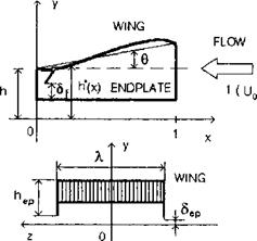 Fig. 4.7. A rectangular wing with endplates in the extreme ground effect.
|
h*(x, t) |
|
dh*(x, t) dt ’ (4.48) |
and, introducing the spanwise averaged potential ф, we obtain
|
h*(x, t) |
Equation (4.48) includes a function дф(х,±/2,і)/дг that represents the transversal velocity component under the wing in the close vicinity of the endplate. For a practical case of symmetrical leakage, when dф/dx(x1 Л/2) = —dф/dz(x, — Л/2), we obtain from (4.48)
We relate the velocity vep of transversal leakage to the spanwise averaged longitudinal velocity d(t>/dx(x, t), assuming that the perturbed pressure outside of the endplate is equal to zero. Let Sep(x, t) represent an effective gap under the endplate (nondimensionalized with respect to the chord). Then the velocity vep of the leakage is given by
vep(x, t) = h*{x, t)^(x, t, ^)/8ep(x, t), (4.50)
and the corresponding dynamic condition just outside of the endplate takes the form
 p(x, t) = U2(t) -vip(x, t) –
|
3ep(%> 0 h*(x, t) |
where U(t) is a function, describing the time variation of the speed of the vehicle cruising. It follows from (4.50) and (4.51) that
= signp(x, t)y/p(x, t), (4.52)
|
h*{ |
|
dh*(x, t) dt |
where p(x, t) is the span-averaged pressure coefficient under the wing. Taking into account (4.51), equation (4.49) takes the form
Equation (4.53) is a one-dimensional description of the flow in a highly contracted channel under the lifting surface with endplates that accounts for the lateral leakage of air through the gaps under the endplates. Essentially, such a description corresponds to a small ground clearance and small (with respect to the characteristic height h above the
ground) gaps under the tips of the endplates. Note that the plus in front of the square root term in (4.53) corresponds to the outward leakage, whereas the minus corresponds to the inward leakage. As accounted for by the signum function in (4.53), the direction of leakage depends on whether at a given moment and for a given station x along the chord, the pressure coefficient under the wing is positive (pressure) or negative (suction). In the former case, the leaking flow is directed from under the wing into the external area, whereas in the latter case, it is directed inward.
Note that the definition of the effective gap Sep under endplate depends on the choice of the flow model of the leakage from under the endplate (or flap).[21]
Two boundary conditions necessary to solve equation (4.53) ought to be determined by smooth blending (asymptotic matching) of the channel flow with local flows near the leading and trailing edges. It has been shown in section 2 by using local flow solutions that for the extreme ground effect case (h 1), an appropriate boundary condition at x = 1 (leading edge), has the form
0(1,0 = 0. (4.54)
From the physical viewpoint condition (4.54) signifies that in the extreme ground effect, the vorticity in the channel under the wing is accumulated (due to the development of the boundary layer), counting from the leading edge.
The boundary condition at x = 0 can be obtained from the requirement of pressure continuity at the trailing edge and by using asymptotic estimates for h —> 0 of the pressure coefficient above the wing p = 0(h) and in the channel beneath the wing p = 0(1). Introducing an effective gap 6f(t) under the trailing edge, we can write the corresponding dynamic condition as
p(x, t) = U2(t) – vj(t) -2^(0,t) =0, (4.55)
where Vf(t) is the velocity of the flow leaking out from under the trailing edge. This velocity is related to that of the channel flow in the immediate proximity of the trailing edge by the flow continuity relationship
g(°,<) = (4.56)
wherefrom taking into account (4.55), we deduce the second boundary condition for equation (4.53) at x = 0:
^(0,0 = -?rWyi^W-2g|. (4.57)
In addition to boundary conditions (4.54) and (4.57), an approprate initial condition should be imposed. For example,
![]() ^(*,0) = vo(®).
^(*,0) = vo(®).
The lift and moment (with respect to the trailing edge) coefficients can be calculated by using the formulas
![]() p(x, t)dx, mz = xp(x, t)dx,
p(x, t)dx, mz = xp(x, t)dx,
Jo
where the pressure coefficient is given by the expression
![]() p(x, t) = U2(t) –
p(x, t) = U2(t) –
On the basis of the solution of a one-dimensional unsteady nonlinear flow problem past a rectangular wing with endplates in the extreme ground effect, we can derive the induced drag coefficient. As previously in the general case, the induced drag is defined as the difference between the pressure drag in inviscid flow and the suction force acting upon the leading edge. Hence, the corresponding coefficient can be written as
C’xi — Cxp + cB,
where CXp is a drag coefficient due to the action of the normal aerodynamic loading in the longitudinal direction (ideal pressure drag) and Cs is the suction force coefficient. To obtain CXp, we project the spanwise averaged pressure forces, obtained within the present theory, onto the longitudinal direction. For a small rear flap, we can determine separate contributions of the wing CXpvr and of the flap CXp{ to the pressure drag of the lifting system. Accounting for the coordinate system adopted in this book, one can derive the following expression for CXpw:
Cxpv(t) = J p(x, t)cos(n, x)dx =-h0 J p(x, t)^dx, (4.59)
where y = y/h0, y = y(x, t) are the ordinates of the points on the lower surface of the wing, measured from the unperturbed position of the underlying surface. In the case of a flat wing, it follows from (4.59) that Cx = —Cy9.
The ideal pressure drag of the rear flap can be obtained by using the solution of Gurevich [138] for the drag of a wedge with streamline separation. Renormalizing the expression of the pressure drag coefficient obtained by Gurevich with respect to the velocity on the (jet) free boundary and the area of the wing planform, we obtain a simple formula for the pressure drag
coefficient of a rigid flap in separated flow [22]
CXp{(t) = h0[l – (t)]2, = S{/h. (4.60)
Now, we can turn to the derivation of the coefficient of the suction force acting upon the leading edge. This force presents an integrated effect of suction, occurring due to the large curvature of streamlines in the vicinity of the leading edge. In principle, the suction force contribution should be determined by integrating the projection of the local suction force over the contour of the leading edge, but it is rather difficult to single out this force numerically. At the same time, calculations show that, as the foil becomes thinner, the local suction increases whereas the radius of the leading edge decreases. These two factors vary so that their product remains finite and almost constant up to the limiting case of zero foil thickness. That is why it is often assumed that the theoretical value of the suction force determined at the leading edge of zero thickness can be utilized for practical rounded edges with a finite radius of curvature. By using formula (2.39), the asymptotics of the flow velocity of the relative motion at the points of the leading edge of the wing in the extreme ground effect can be written as
~J~T = cli + О {hi), (4.61)
where (pae is determined by formula (2.42). Matching (4.61) with the channel flow velocity v(x, t) and accounting for the asymptotics of (2.47) leads to the following expression for a\
a = h*(l, t)[U(t) +i(l,£)]. (4.62)
Substituting (4.62) in formula (2.113) to determine the suction force on a wing in the extreme ground effect, we obtain
= ЬотЙ^г = h0h*(l, t)[U(t) + v(l, t)}2. (4.63)
ft (M)
Eventually, the induced drag coefficient can be written as
cxi(t) = h0{h*(l, t)[l + V(l, t)}2 – da:- [1 – 5f(*)]2}. (4.64)
Examples of calculation of the induced drag coefficient for particular cases will be presented later.
Thus, a one-dimensional nonlinear formulation has been found for the aerodynamics of the longitudinal motion of a rectangular flying wing with
endplates in the extreme ground effect. This formulation includes equation (4.53), boundary conditions (4.54) and (4.57), and initial condition (4.58). This mathematical model accounts for unsteady effects, which can be caused by motions of the wing as a rigid or deformable lifting body, the action of control devices and wind-wave perturbations. Though sufficiently simple, it retains the inherent nonlinearity of the aerodynamics of the extreme ground effect with respect to the geometry and kinematics of the lifting system. The common sense basis of simplifying the flow model consists of the observation that when the endplate tip clearances are very small, the channel flow, already ’’squeezed ” vertically for h —> 0, becomes almost one-dimensional.
This formulation can be used to evaluate the aerodynamic characteristics and preliminary design of a flying wing configuration for both cruise and power augmentation performance. Note that equation (4.53) describes the main contribution to the aerodynamics of the wing-in-ground-effect vehicle, namely, that of the channel under the main lifting surface. The contribution of the upper surface of the wing can be added, using the general asymptotic approach presented in section 2. Alternatively, due to experimental evidence that, in close proximity to the ground, the upper surface pressure distribution varies insignificantly with variation of h, the upper surface characteristics can be, with a certain degree of approximation, borrowed from the unbounded fluid case.
