Boundary Layer Control in Supersonic Inlets
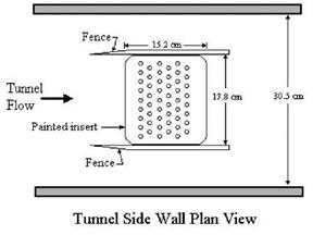
Bencic (2002) applied PSP to boundary layer control experiments in supersonic inlets through mass removal in the 1×1 foot Supersonic Wind Tunnel at NASA Glenn. The tests investigated shock/boundary-layer interactions that caused a reduction in the inlet performance due to boundary layer separation. As shown in Fig. 9.31, the test setup consisted of a porous boundary layer control device replacing a wind tunnel sidewall panel. The boundary layer bleed used a pressure difference generated by a suction plenum mounted to the backside of the porous surface to remove the low momentum fluid in the boundary layer.
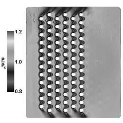
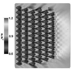
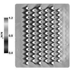
The bleed control panels were painted with a silicone-based Ruthenium PSP (Boeing PF2B). Reference images were taken at reduced pressure of approximately 12 kPa since this facility had the capability to be brought to near vacuum conditions quickly. The reduced reference pressure was used because it was in the range of pressures measured on the porous plates during wind tunnel operation. A constant exposure time was used for both the wind-off and wind-on images, producing images that filled about 80% of the full-well capacity of the CCD camera. Each image was ensemble average of eight frames to further reduce the photon shot noise. Reduction of the acquired data was performed using the intensity-based method plus in-situ calibration based on data from 16 pressure taps located in the painted sections. Typical PSP images are shown in Figs. 9.32, 9.33 and 9.34 for three surface bleed configurations C1, C6 and C3 that denote the standard 90° bleed hole configuration, the pre-conditioned 90° bleed hole configuration and the 20° inclined bleed hole configuration, respectively (Willis et al. 1995). Each image was acquired at a nominal tunnel speed of Mach 2.0 under the similar conditions of the total mass flow through the bleed hole regions.
The PSP images show the surface pressure normalized by the wall static pressure measured upstream of the fenced porous plate insert. The orifice and row interactions, which were clearly evident in these figures, were undetectable with conventional pressure tap instrumentation. The significant result from this test was the performance increase of 50% in removing mass by the pre-conditioned 90° configuration compared to the standard 90° orifice as reported by Willis et al.
(1995) . This increase was due to a combination of flow turning and the pressure gradient acting across the flush inlet. The performance differences between these configurations can be seen as larger pressure excursions as noted by the change in lower scale in Figs. 9.32, 9.33 and 9.34. The more efficient configurations in Figs. 9.33 and 9.34 generally showed a higher level of interaction between adjacent rows compared to the standard 90° configuration in Fig. 9.32. The PSP measurements had an error of 0.3 kPa or less in these examples. A systematic shift was found between PSP and pressure tap data in the bleed hole region compared to the solid region upstream and downstream of the porous region. This shift was due to a temperature difference in the aluminum insert plate caused by the airflow through the orifice holes. Clearly, simultaneous full-field temperature measurements (TSP or infrared thermography) are needed to compensate for the temperature sensitivity of PSP to minimize the errors associated with the effect.
The experiments of Bencic (2002) represent a typical PSP application to complicated geometric configurations in turbomachinery flows. PSP provides a powerful diagnostic tool for turbomachinery flows with complex shock wave structures where a pressure field cannot be mapped with conventional techniques in a high spatial resolution. PSP has been used for pressure measurements in narrow supersonic channel, shock/wall interaction, stator vanes, transonic fan cascade, mixer-ejector nozzles, and jet/flow interaction (Lepicovsky and Bencic 2002; Taghavi et al. 1999; Lepicovsky 1998; Lepicovsky et al. 1997; Cler et al. 1996; Everett et al. 1995). However, confined spaces by multiple surfaces in turbomachinery cause significant inter-reflection of the luminescent light between neighboring surfaces and this self-illumination complicates the data processing to extract correct values of pressure on these surfaces. So far, a correction scheme for the self-illumination was made only for simple geometric configurations such as a corner between two planes. For complex geometry in turbomachinery, an efficient numerical scheme for correcting the self-illumination effect have to be developed based on an accurate model for the bi-directional reflectance distribution function of PSP (see Section 5.3).
|
|
|
|
|
|


