Boundary-Layer Displacement Thickness
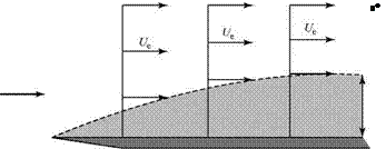
We consider an external flow streamline well away from the edge of a boundary layer growing on a flat plate, as depicted in Fig. 8.12. Because the flow within the boundary layer is moving slower than the freestream due to the action of viscosity, continuity requires that h2 > hi and the external streamline is displaced (slightly) from the horizontal. (The same effect was shown in Example 3.6 when considering the decelerated flow in the wake of an airfoil, with the control surface defined as a streamline.) The displacement thickness is a measure of how far the external flow streamlines are displaced away from the plate surface due to the presence of the boundary layer. The displacement thickness is defined by the expression:
In Eq. 8.69, the left side is set equal to the difference between the mass flux above the plate if there were no boundary layer, Term [2], and the mass flux above the plate with the boundary layer present, Term [3]. Thus, Term [1] represents the mass flux deficit (or defect) in the boundary layer caused by viscous action retarding the local-flow velocity.
 |
 |
|
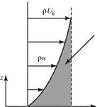
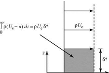
To interpret the definition, Eq. 8.70, physically, we consider Fig. 8.13. On the left is a Blasius velocity profile. On the right is a step profile that has u = 0 up to a height z = 5* and then an instantaneous change in velocity to the full external velocity Ue. Both profiles have the same mass-flow-rate (i. e., mass-flux) deficit. Thus, the mass-flux deficit due to the presence of the boundary layer, which causes the displacing of the flow streamlines outward, can be represented as the outward displacement of the solid surface by an amount 5*. A new effective body shape results, shown in Fig. 8.14, consisting of the flat plate plus an additional curved solid shape 5*(x).
 |
|
This discussion may be generalized to consider an airfoil in a viscous flow operating below the stall. The pressure distribution on the airfoil is calculated by using an inviscid-flow model. Then, the boundary-layer equations are solved for the velocity profile within the boundary layer (by methods discussed later) and, hence, S* may be evaluated from Eq. 8.70, which is valid for laminar or turbulent boundary-layer flow. This displacement thickness then is added to the airfoil shape (as S* was added to the plate) and a first iteration is carried out by calculating the pressure distribution on this equivalent airfoil shape using potential flow methods. A new S* follows and the process is repeated until a satisfactory convergence is achieved. Because S* normally is small, only a few iterations are required.
|
s*-J|1 – U d-J|1 – f |
|
2 г* |
The displacement thickness for a laminar boundary layer on a flat plate can be evaluated from the Blasius solution. In this case, Eq. 8.70 becomes:
This integral can be evaluated numerically to yield:
![]() (8.72)
(8.72)
where, again, x is the distance from the leading edge of the flat plate. This is a useful result in that it accounts for the presence of the boundary layer, and the expression is unique.
Boundary-Layer Momentum Thickness, 0
This parameter is defined in terms of the momentum deficit in the boundary layer rather than the mass deficit used in defining the displacement thickness. Thus,
![]() pf/^ =JpuUedz – Jpu2dz,
pf/^ =JpuUedz – Jpu2dz,
00
or, for incompressible flow:
In Eq. 8.73, Term [1] represents the momentum of flow within the boundary layer if the mass in the boundary layer has a velocity Ue, whereas Term [2] represents
the momentum of the boundary-layer flow if the boundary-layer mass has a velocity u. Thus, by this definition, the momentum thickness, 0, represents a thickness of the freestream flow that has a momentum equal to the momentum deficit in the boundary layer. The quantity cannot be understood physically as easily as 5*, but it is useful in later discussions.
Evaluating Eq. 8.74 from the Blasius boundary-layer solution yields a unique expression:
|
5* |
The ratio of the displacement thickness to the momentum thickness of a boundary layer is called the shape factor, H; that is:
Shear Stress on the Wall, tw
An important feature of the formation of a boundary layer on a surface is that there is a surface traction (i. e., a force parallel to the surface) in addition to the normal force due to the pressure. This can be an important source of drag on the body. Recall from Eq. 8.10 that in the boundary layer, the shear stress at any point in the flow is proportional to the rate at which the parallel velocity changes normal to the wall, du/dz. In particular, at a wall, the shear stress is:
This shear stress is a viscous (friction) force per unit area acting in a tangential direction on the surface. Therefore, it is a local boundary-layer property, dependent on x. Differentiating the Blasius solution for u(z), we find:
![]()
![]() (8.78)
(8.78)
The average shear stress on the wall over a length interval x = 0 to x = L then is given by:
![]() = 7 fTwdx.
= 7 fTwdx.
0
Notice that the factor 1/L is required in the definition so that if an average value is assumed for tw over the interval, then the definition is consistent. Applying Eq. 8.79 to a Blasius profile:
where the Re number is formed with the length L. This average wall-shear stress acts on the surface area of a flat plate of length L (per unit width).
Friction Coefficient, Cf
The friction coefficient is a dimensionless expression for the wall shear stress, defined as:
![]() T
T
(8.81) so that, for the Blasius profile:
~ _ (0.664)
Cf _~fr^ ■ (8.82)
V Rex

The average friction coefficient for a surface over the length x _ 0 to x _ L is given for the Blasius profile by:
example 8.1 Given: A thin-wing model at a small angle of attack (approximate by a flat plate) has a chord length of 2 feet and a span of 10 feet. The wing is tested in an air stream of 100 ft/s at standard conditions. Assume a Blasius solution for the wing boundary layer and assume two-dimensional flow over the entire wing span.
Required: Find the frictional drag force on the wing (both sides). Give the units of the answer.
Approach: Calculate the drag by first evaluating the average wall shear stress from Eq. 8.74 or Eq. 8.76.
Solution: Evaluating Eq. 8.76 using standard atmosphere values of p and v:
_ _ (0.664)(0.00238)(100)2 _ 0093lbf.
w V(2) (100) (0.0023 8)/ (3.72-10-7) ft2
An estimate of the viscous drag of the plate is then:
D = Tw (L)(width) x (2 sides) _ 40tw _ 3.72 lbf.
Appraisal: In calculating the drag, the average wall-shear stress must be used because the local stress is a “point” property. Check the units of the answer. Also, note that drag force is viscous stress times area. Accounting for the two sides of the wing is equivalent to stating that this is the frictional drag of the wing “wetted” area—that is, the total wing area exposed to the flow.
The experimental value of the local-friction coefficient for a flat-plate laminar boundary is about 0.001 at a Re number of 500,000. This experimental result and the prediction of Eq. 8.82 agree to within 6 percent. The experimental measurement is difficult (Liepmann and Dhawan, 1951), involving the direct measurement of the
shear force acting on a small section of the flat plate. When the turbulent boundary layer is discussed later in this chapter, it is found that the turbulent-velocity profile is fuller near the wall than the laminar profile; that is, near the wall, utorb > ulam. This implies that the wall shear stress and, hence, the frictional drag, is larger for a turbulent boundary layer than for a laminar boundary layer.


