CHARACTERISTIC DATA
Some of the detailed test data on low aspect ratio wings confirm the concepts discussed in the previous section. However, because of the many variables involved it is difficult to determine that portion of the non-linear lift curve, yaw effects, maximum lift and compressibility effects of low aspect ratio wings. Thus, some of the available experimental data relating to these problems are presented in addition to the data given on figure 5.
Circular Planform. Disks and circular “wings” are an extreme of round planform. Available experimental data are plotted in figure 8. Sharp-edged plates have a linear lift-curve slope as high as indicated by the upper line in figure 3. The Clark-Y profiled wings (ll, b) are at least in the forward 50% of their lateral edges rounded; and their lift is reduced accordingly, to the lower limit as in figure 3, at A = 4/rr = 1.27. If the cross section shape is viewed based on drag it appears the wings with the flat tops should have the highest lift. This is generally true as noted in figure 8.
Ellipsoid. When increasing the thickness ratio of a disc, we may arrive at bodies similar to those in body (A) of figure 8. Such shapes have been wind-tunnel tested in (11 ,c, d,e) with stabilizing flaps and fins attached, for possible use as re-entry vehicles (from outer space). To us, the ellipsoid in the graph, is the perfect example for the life-reducing effect of rounded trailing and lateral edges of any wing. As a matter of interest, the maximum (L/D) ratio of the shape shown is 10, at CL = 0.2. Effectiveness can greatly be improved by horizontal tail flaps (11 ,d, c) which are necessary anyhow to stabilize and to control the body when really used as a vehicle.
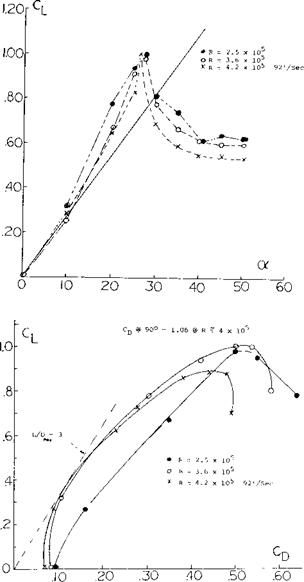
The Discus. Disregarding any dreams of “flying saucers”, the athletic implement called discus seems to be the only practical application of a circular planform. The ballistics and aerodynamics of the discus have been investigated by Ganslen (12,b). Figure 9 presents the aerodynamic forces. The lift shows clearly an initial linear slope and a non-linear movement. Stalling takes place at of =29 . The normal force resumes growing above
40 ° , reading at 90 the drag coefficient C D =1.06. The pitching moment (not reported) is certainly “up”. The longest distances, some 60 meters, throwing a discus are obtained when launching at some 35 (against the horizontal) but at an angle of attack (against air) slightly below zero. The rotation imparted when properly throwing (some 6 revolutions per second) stabilized the discus, thus minimizing the pitchup (against the horizontal). The ballistic trajectory necessarily ends, however, at an angle of attack above 35 , that is in stalled
condition. At least part of its way, the discus is, nevertheless, gliding at an (L/d) ratio reaching a maximum of 3, at = 10 (against the air).
|
DISCUS CROSS SECTION |
|
|
Figure 9. Lift and drag characteristics of discus.
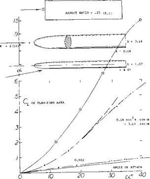
Streamline Body. The flat body as in figure 10 may be a streamline body. As such it should be discussed in the chapter on this subject. However, we can also claim this body to be a low-aspect-ratio wing with rounded lateral edges. Doing so, it must be noted that there is a straight and blunt trailing edge. The non-linear component is only ( ACj_ /sin2- of ) = 0.15, for A = 0.16. As seen in figure 10, this is the lowest point near A = zero.
The well-rounded shape in combination with a high Reynolds number is evidently responsible for this result. The flow simply gets around the lateral edges. By comparison, a sharp-edged flat plate having approximately the same aspect ratio exhibits twice as much non-linear lift as the round body. The linear lift component is also low for the flat body, around Vi the theoretical value as in figure 3. It is suggested that the blunt (and sharp) trailing edge of the body prevents this component from being still lower.
|
Figure 10. Lift and drag characteristics of a flat streamline body (10,b). |
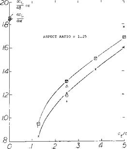
Tests of flaps on rectangular wings with A = 1.25 from (13,a) figure 12 show that below a flap to wing chord ratio Cf / C = .25 the lift slope is not linear. This tends to confirm the data of figure 11 and also shows the importance of the trail edge shape or angle on flap effectiveness.
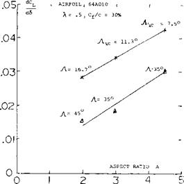
The characteristics of flaps as a function of aspect ratio is given on figure 13. For the 30% chord flaps tested in (13,b) the effectiveness is reduced with both A’ratio and sweep angle. With a reduction of A’ratio below 2 it is expected that 30% flaps will be even less effective than the trend illustrated on figure 13.
Horizontal Tail Surfaces. Low and moderate aspect ratio wings are used as horizontal tail surfaces. Available experimental results for such surfaces are given on figure 14. In some applications gaps are found for the rudder and the planform is rounded. The use of a correction factor a of.85 for the surfaces without gaps and.75 with gaps results in good correlation of the experimental data. Further discussions of the characteristics of tail surfaces are given in Chapter IX.
|
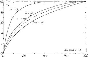
Figure 11. Ratio of CL c, lift to a given chord station to the total lift coefficient C L j, for a rectangular wing of A = .25. |
 Flap Characteristics. As previously noted the area of a small A’ratio wing aft of its maximum effective width does not produce lift. This occurs as explained in (l, i) because the down wash produced by the sections in front of the maximum effective width will operate in a flow field equal to the angle of attack of the section. Thus, the flow becomes parallel to these sections. The ratio of the lift to the total, CLC / CLT, as measured in (5,c) is given on figure 11 as a function of chord length. For the flat plate rectangular wing, operating at = 10° , 95% of the lift is generated on 60% of the wing chord. Thus, the effectiveness of the area where flaps would be used is reduced and we would expect that flap effectiveness would also be less.
|
|
 |
|
|
|
|
|
|
|
|
|
|
|
|
|


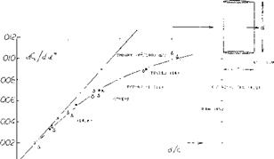
Aspect Ratio. Referred to the area S = d c CL = 7Y(d/c) sinot ; dCL /dot = (24)
( rr2/180)(d/c) = 0.055 (d/c)
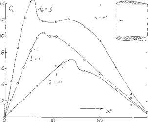 Experimental results in figure 17 confirm the equation (24) very well. Regarding the airfoils as in figure 17, the effective diameter is questionable in connection with the highly cambered Clark Y foil section. We have assumed a d/c = 0.1 to account for some of the airfoil thickness corresponding alternate points are included in figure 17. Agreement with the “sharp” rectangular wings in figure 3 is obtained at small aspect ratios, when referring C l. to the area (2 d c). This result means physically that the volume of air affected (deflected) by the ring wing corresponds to a stream cylinder with a cross-section area two times that of the opening area of the ring.
|
|
|
|
|
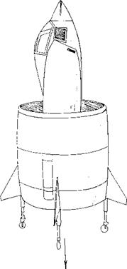
Figure 15. Jet-powered French VTOL aircraft SNECMA “Coleopter”, as shown on the cover of Newsweek 5 Oct. 1959.
(14) Characteristics of small aspect ratio ring wings:
(a) Weissinger, Ring-Wing Theory; Rpts 2,39,42 (1955/57) of DFL; and ZFW 1956 p 141; also USAF OSR TN 1958-224.
(b) Richter, Ring Aerodynamics, Yearbk WGL 1955.
(c) Fletcher, 5 Annular Foils, NACA TN 4117 (1957).
(d) As developed in France, see Seibold, Ring Plus Machinery, Yearbk WGL 1954 p 116.
(e) Weissinger, Ring Plus Body, AFOSR TN 60-343 (1960).
|
|
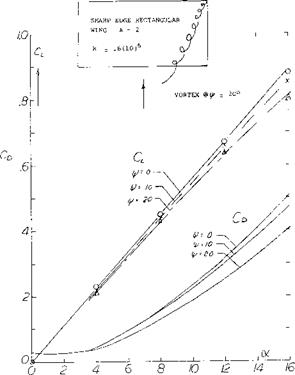
Figure 18. Lift and drag characteristics of a low aspect ratio wing operating at yaw angles.
EFFECTS OF YA W. The influence of the wing tip on the characteristic of low aspect ratio wings operating in yaw can be large. For instance, a rectangular wing with an aspect ratio of one becomes a double delta or diamond shaped wing with the one tip becoming the leading edge. Thus, if the wing were operating at a yaw angle of 45° the tip shape would have the same influence as the original leading edge. When operating at a yaw angle the vortices at the tip become influenced by the tip sweep angle.
(15) Effect of yaw on low aspect ratio wingsi
(a) Schock, Low A’ratio Wings with Sharp Leading Edges, Princeton Aero Eng Report No. 574.
(16) Compressibility effects:
(a) Ferri, Elements of Aerodynamics of Supersonic Flows, Macmillan Co. 1949.
Smoke surveys (15,a) on a rectangular wing of A = 2 indicated that position of the tip vortices are influenced by the yaw angle as well as the angle of attack. Typical results are given on figure 18. Note that with increasing lift the vortices move inward from the tip but the movement is less as yaw angle is increased. The upstream vortex height decreases with angle of attack, while the vortex from the downstream decreases in height. From figure 18 it will be noted that both the lift and drag decrease with increasing yaw angle. If the effective aspect ratio or span is considered it would be expected that the lift would increase with yaw angle as indicated by equation 7.


