Comparison of Near/Far-Field Formulas
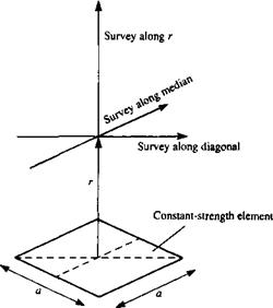
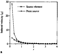
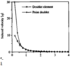
To demonstrate the possible range of applicability of the far-field approximation, the induced velocity for a unit strength rectangular source or doublet element, shown in Fig. 10.16, is calculated and presented in Figs. 10.17-10.22 (figures based on Browne and Ashby102). The computed results for the velocity component parallel to r in Fig. 10.16 versus distance r/a (where a is the panel length as shown in Fig. 10.16) clearly indicate that the far-field and exact formulas converge at about r/a >2 (e. g. Figs. 10.17 or 10.18).
Similar computations for the total velocity induced by a doublet panel are presented in Fig. 10.18, and at r/a > 2 the two results seem to be identical.
FIGURE 10.16
 Survey lines for the velocity induced by a rectangular, flat element.
A velocity survey above the panel (as shown in Fig. 10.16) is presented in Figs. 10.19-10.22. Here the total velocity survey is done in a horizontal plane at an altitude of z/a =0.75 and 3.0, along lines parallel to the panel median and diagonal.
These diagrams clearly indicate that at a height of z/a = 0.75 the far-field formula (point element) is insufficient for both the doublet and source elements. However at a distance greater than z/a = 3 the difference is small and numerical efficiency justifies the use of the far-field formulas.
 FIGURE 10.17
Comparison between the velocity induced by a rectangular source element and an equivalent point source versus height r/e.
FIGURE 10.18
 Comparison between the velocity induced by a rectangular doublet element and an equivalent point doublet versus height rja.


