COMPRESSIBILITY
Low aspect ratio wings are used for high speed aircraft because of the delay of the drag rise and improved performance at Mach number above 1.0. The change in the Mach number for the drag rise and the drag at high speed of low aspect ratio wing is given in the book “Fluid Dynamic Drag”.
LIFT AT M < 1. Compressibility encountered at higher subsonic speeds affects the sectional lift angle, that is, in large-aspect-ratio wings, see Chapter VII. For slender wings (say, below A = 1) the formulation (l, i) predicts that compressibility does not have any influence upon the linear, circulation-type lift component. According to the Prandtl-Glauert rule, any wing reacts as though its chord would be lengthened in proportion to the Prandtl factor
“P” = 1/ ^1 -Мг = l/p (25)
This means that the effective area is increased and the aspect ratio decreased. According to Equation 5, the lift-curve slope is not affected by these variations.
In aspect ratios above A == 1, there is a transition between the two extreme ranges considered above. It may be instructive, however, to use equation 23 with a modified Prandtl function reducing the sectional angle of attack for low lift coefficients
dcz /dCL = (10 + 8/A2 ) (1 – М2)П + 20/A (26)
![]()
![]()
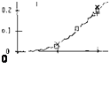 The exponent varies between zero at A well below unity, and n = 0.5 for higher aspect ratios. We have evaluated available experimental results (16). After excluding various points which simply cannot be right, the most likely function of n is as in figure 19.
Non-Linear Lift. The effects of compressibility on the non-linear component of lift is not described by any available theory. If the increase is due to drag based on the flow normal to the wing it would be expected that the component would not change at Mach numbers below 1. Нс ‘ >ег, if the component also depends on the cross sectional area and this is effectively increase by compressibility, the non-linear component 1 should increase with Mach number. Thus the к determined from figure 7 would be modified for compressibility by the equation
к = P £Cl /sin2o’ (27)
where P = 1/(1 – Mz )n and n is the Prandtl-Glauert factor modified by A’ratio given on figure 19. More study and experimental data is required to confirm equation 27.
ASPECT RATIO A [131] [132]
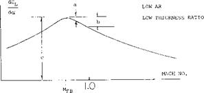
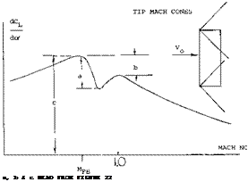 Transonic Range. Above the critical Mach number the lift curve slope of low aspect ratio wings is reduced by the formation of shock waves on the upper surface. These shock waves effect the lift in the same manner as for a two dimensional wing, Chapter VII. The result of this is a sharp reduction of lift after the critical is reached with a recovery at approximately M = 1, as illustrated on figure 20. The Mach number at which the lift slope break occurs is a function of the aspect ratio and the angle of sweep.
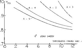
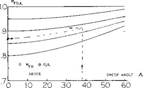
For straight wings this Mach number can be estimated using figure 21. The minimum lift slope will be obtained at
MLm =d+MLBf (28)
(17) Low aspect ratio wing tests including CL x:
(a) Nelson, Wings on Transonic Bump, NACA IN 3501.
(b) Nelson, 38 Cambered Wings, NACA TN 3502 (1955).
(c) Nelson, 36 Symmentrical on Bump, NACA TN 3529.
(d) Nelson, 65-210 Wings with A = 1 to 6, NACA RM A 9K18.
(e) Allen, Plan-Form Body Taper Effects and Mach No. Effects A = 2, 3 and 4, NACA A53C19.
(f) Jones, Low Speed Tests Rectangular Planform A = 1, 2 and 3 Wings, NACA RM L52G18.
(g) Dods, Test of Nine Related Horizontal Tails A = 2 to 6, NACA TN 3497.
(h) Graham, Large Triangular Wings, NACA RM A50A04a.
(i) Zimmerman, Clark Y Airfoils of Small A’ratic. NACA TR 431.
|
|
Figure 20. Typical variation of lift curve slope in the transonic range with associated shock waves.
|
|
|
|
Figure 21. Charts for calculating force break Mach number of straight and swept wings.
SUPERSONIC RANGE. At Mach numbers above those where the shock waves are attached to the wing, theory (16,a) provides a good insight into the performace of wings. At low lift coefficients the linearized theory gives for the lift curve slope the equation
dCL _ rr / 1
^ AS Jut – 1 2kjuz – Г*29)
This applies to rectangular wings where the center port ion of the wing is operating in two dimensional flow and the tips are within the Mach cone as illustrated in figure 23.
It is expected that as in the subsonic range a non-linear component of lift will be generated that will add to that of equation 29.


