Cylindrical probe
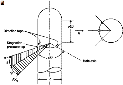
The probe consists of a cylinder perpendicular to the stream on which three holes are drilled, the central one for the measurement of stagnation pressure (Figure 2.23). The probe has a sensitivity of about 0.05 per degree.
As can be seen from Figure 2.2, the separation of the wake also changes the distribution of pressure in the upstream part of the cylinder and also in different ways according to the flow regime, laminar or turbulent. If the null reading method is used, that does not lead to errors because the situation is symmetrical about the axis, problems arise in the transitional regime in which there are oscillations of the wake and thus in the pressure.
 |
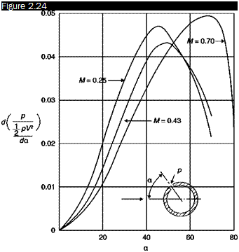
The sensitivity of the instrument depends on the position of the holes (Figure 2.24): at low Mach numbers, it is highest when the holes are placed at ±45°; for higher Mach numbers, the optimal angle increases, e. g. at M = 0.7 would be about ±70°. The critical Mach number, not to be exceeded, is 0.55.
 |
Effects of positioning of holes on a cylindrical probe at different Mach numbers
In a 3D version, a fourth hole on the cap that closes the cylinder is used to measure the pitch angle from the difference between measured pressure and stagnation pressure. This probe is small and is therefore used for measurements in tight spaces such as those typical of turbo machinery blades. Because of the distance between the holes, it is not very accurate in the presence of velocity gradients.


