Fuselage Side-Forces
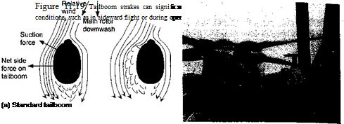
The origin of the adverse download and pitching moments on the airframe that are induced by the rotor has been discussed previously in Section 11.2.2. However, adverse side forces can also be produced on the airframe as a result of the rotor wake. An example has been shown previously in Fig 11.11, where the difference in static pressure between the two sides of the tail boom will produce a net side force. The side force is usually in the direction opposite to that required for anti-torque purposes. It has also been shown that when a helicopter is in sideward flight or is hovering over a fixed point above the ground in a crosswind, a significantly increased side-force will be produced on the fuselage. For most helicopters this side-force usually remains small enough to have a minimal impact on the handling qualities of the helicopter and its operational envelope. However, in some cases, the adverse aerodynamic side-force can be significant and may impact flight operations. This can occur when the helicopter is in starboard sideward flight or has a starboard crosswind component – see Fig. 11.19. (This example is for a rotor turning in the conventional, counterclockwise direction.) On some helicopters this is a powerful adverse effect that can affect directional (yaw) control and can limit its operational flight envelope. In particular, this can be an issue on military helicopters as these must often demonstrate high-speed sideward flight capability and must often operate in confined locations in gusty crosswind conditions (such as on a ship).
The aerodynamic side-force on the fuselage has been found to be accentuated by certain tail boom shapes, which can produce a sizable circulatory lift forces when the sideward velocity is combined with the main rotor downwash – see Wilson & Kelly (1983, 1986) for a systematic study of the forces produced on such tail boom shapes. See also Delany & Sorensen (1953) and Hoemer (1965) for force measurements on a variety of bluff body shapes. To counter this undesirable side-force effect, Brocklehurst (1985) and Wilson et al.
 |
(b) Tailboom with strake (c) Application on a helicopter
(1988) have suggested the use of a spoiler or strake that runs longitudinally along the one side (usually the port side) of the tail boom. This strake forces the flow to separate from the tail boom surface, spoiling the side-force and thereby restoring or improving the helicopter’s operational flight envelope – see Kelly et al. (1993). This design solution will only be required if the tail boom cross section is relatively deep, typically if of quasielliptical shape with height to width ratios greater than about 2. The strake also creates a vertical download penalty and a nose-up moment on the airframe, but these effects are relatively small compared to the overall operational benefits that have been realized with me use oi а аігаке. inis uevice nas uceii iiueu or reiroimeu to several prouucuon nencopier models. A more recent innovation is to use tail boom venting with porous skins to reduce tail boom side forces – see Banks & Kelly (2000). Although, passive venting appears to reduce adverse side-forces, its use is also accompanied by an increased vertical download from the higher skin friction effects created by the flow as it passes over the porous skin.


