MAXIMUM LIFT
The maximum lift characteristics of straight and swept wings with a high aspect ratio are given in Chapters IV and XVI. Because of the greater influence of the tips, the planform shape of low aspect ratio wings is the dominant factor influencing the CLX and angle of attack at which it occurs. The actual airfoil section used is of secondary importance :in determining C L* , especially with very low aspect ratio wing, A < 1.
Theoretical Maximum. The theoretical maximum lift of two dimensional wings was shown in Chapter IV to be 4 FT but could not exceed the value described by
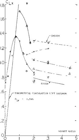
CLx =1.94 A (30)
Equation 30 gives the maximum lift that could be expected by flow circulation. For very low A’ratio wings the actual C LX exceeds that of equation 30 because of the secondary lift term. This is illustrated on figures 6 and 22 for a rectangular wing with A = 0.2 where C LX is .95 compared to the expected maximum value from equation 30 of.388. Near C the secondary lift term caused by the flow normal to the wing was larger than the circulation lift term and results in a CLx ~ .562.
The maximum lift and stalling characteristics of low aspect ration wings vary widely as shown on figures 5, 6 and 8. Since the stalling process is due to separation and is influenced by the secondary lift of the wing, theoretical solutions are lacking.
Variation of С^л With Aspect Ratio. In figure 23 the CLx is given as a function of aspect ratio from the test data of (17). In the range of A – 3 comparison of the data with that presented in Chapter IV indicates that to estimate CLX in this range the more extensive empirical data given in the chapter on stalling should be used. Below an aspect ratio of 2 C Lx appears to increase with decreasing A’ratio until the theoretical maximum is obtained and then starts to decrease. The data on figure 23 again illustrates further examples of C exceeding the theoretical maximum In the lower aspect ratio range A 1, C LX appears to be nearly insensitive to the section configuration, although the tip configuration appears to be important. Wings with rounded tip tend to have higher values of CLX than square tip wings.
|
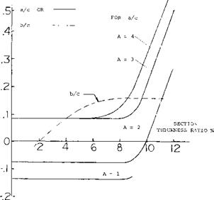
a, b and c CORRESPOND TO dCL/dcY AS IN FIGURE 2 0- |
Figure 22. Data for estimating critical points of lift curve slope in transonic range.
At A above 1.5 there is a large variation of CLX
which depends on cross section, taper ratio and hading edge sweep angle. Tip shape also appears as an important parameter influencing C|_x • The condition of the leading edge and, therefore, Reynolds number effects CLX, the change being similar to that noted in Chapter IV where airfoils tested in the smooth condition show a AClx 0.3 to 0.4 above the value tested in the rough condition. Except for those points noted the data given in figure 22 should be assumed to correspond to the rough leading edge condition.
Type of Stall. The test data given on figures 5, 6 and 8 show that the stall can either be very sudden or rounded. At A ^ 3 the type of stall appears to depend
on the leading edge radius as discussed previously. When the wing has an A’ratio below 2 the shape of the leading edge has little influence and both sharp and well rounded types of stall are observed. It does appear that when the C^_x exceeds that expected based on the two dimensional section, the stall will be very sharp. This is illustrated for the wings using Clark Y sections.
|
FLAT PLATE |
II o’ II < |
1.0 |
RN.45 to 1.8(10)6 |
(17,h) |
|
NACA 6ЗАО04 |
A = 0, Л = |
1.0 |
RN=1.25 – 1.70(10)6 |
|
|
NACA 6ЗАО06 |
-A = 0 > = |
1.0 |
||
|
63A010 |
JV =16.7 to |
7.6, |
A= .5 3(10)6 |
(17, g) |
|
63A010 |
A = 35° to |
45° |
(17, g) |
|
|
NACA 0012 |
LE = ROUGH |
(17,f) |
||
|
NACA 0012 |
LE = SMOOTH |
|||
|
CLARK Y |
SQUARE TIPS |
(17,i) |
||
|
CLARK Y |
ROUND TIPS |
(11, b) |
||
|
CLARK Y |
ROUND TIPS |
(11,b) |
||
|
FLAT PLATE IN WATER, FIGURE 6. |
|
|
Figure 23. Maximum lift of small aspect ratio wings including theorectical maximum for circulation lift.


