Near-field force and moment calculation
 |
|||||
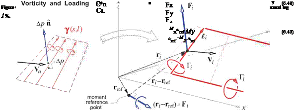
Once the Гг strengths are known, the normalized velocity relative to the midpoint гг of the i’th h. v. is calculated, as shown in Figure 6.9. This uses the same form as (6.32),
except the h. v. kernel functions Vj here are different than those in the flow-tangency condition (6.34), since the bound-leg midpoint locations гг are different from the control-point locations rC. In the Vj function in (6.42) it is also necessary to omit the bound leg’s contribution on itself, which is the first term in (6.33), since this is singular at гг.
 |
||||
The normalized force Fг on each h. v. is computed by the integrated form of the local pressure loading relation (6.22).
The last step in (6.44) consists of lumping the vortex sheet on the element into the element h. v.’s bound leg vortex segment, 7 dS ~ ^Гг. The relevant quantities are shown in Figure 6.9.
Interestingly enough, the Kutta-Joukowsky force calculation form (6.45) gives exactly zero drag in the 2D case where there are no trailing h. v. legs. Therefore it implicitly accounts for the leading edge suction force, which then does not need to be added explicitly.
The total normalized force and moment on the whole configuration are obtained by summation of all the individual h. v. contributions. The moment is defined about a specified point rref.
|
N
|
The standard dimensionless force and moment coefficients in stability axes, shown in Figure 6.2, are obtained by rotating F and M using the T matrix given by (6.5). The reference span and chord bref, cref are
 |
also used here to non-dimensionalize the moments.
If there is a nonzero sideslip, в = 0, then the physically correct expression for the induced drag coefficient is given by the wind-axis relation (6.8).
![]() Cd = – F ■ U
Cd = – F ■ U


