Power Requirements
For the static case (CT -> oo) and
JjL . (9.24)
Р1р„р t JtpJa
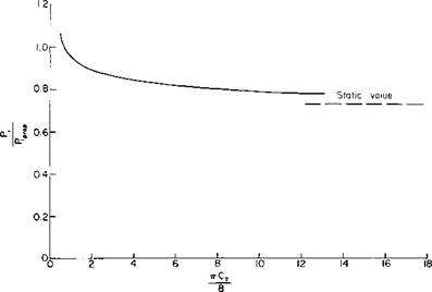
Equations (9-23) and (9-24) have been evaluated for the duct of Fig. 9-11 by using the value of T/TR and VR/V given in Fig. 9-12 (including the effect of shroud drag). For this particular case PJP1 is presented in Fig. 9-14 as a function of the total thrust coefficient. The ducted propeller is seen to be superior to the open propeller above a value of nCT/8 of approximately
|
Fig. 9-14. Ratio of ideal power required by ducted propeller to ideal power required by rotor acting as open propeller (for duct in Fig. 9-11). |
0. 65. For the static case for the same total thrust the ducted propeller requires about 27% less ideal power.
Design of Rotor
This section considers briefly the design of the rotor. For a more complete treatment consult the many available references (e. g., [4]).
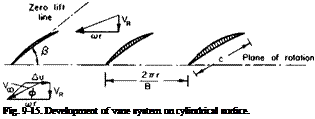
Unlike propeller design theory, which corrects two-dimensional airfoil theory for the effect of the trailing vortex system, the ducted rotor design can be based on the application of cascade data. The development of a cylindrical surface of radius r concentric with the axis of rotation is shown in Fig. 9-15. Each section is acting under the influence of a rotational
|
<> + =7*) |
 |
|
velocity, tor, and an axial component, VR. In addition, the fluid is given an additional tangential velocity. An, after passing through the cascade of airfoils. For such a cascade of airfoils lift and drag coefficients are based on the velocity Vx, which is the resultant of VR, cor, and Au/2. Thus the thrust and power of В blades can be written in integral form as
where £ = CJC,.
 |
The tangential velocity A и can be related to the pressure increase across the vane system Ap through the power. For an annular streamtube of cross-
sectional area 2nr dr passing through the vane system the rate of change of angular momentum is equal to the differential torque dQ. Therefore
rp(2nr dr)VR Am = dQ ;
but to dQ must equal the incremental power given by the product of Ap and the flux of fluid through the streamtube. Hence
corp(2nr dr)VR Am = Ap(2nr dr)VR
or
Equation (9-26) is often referred to as Euler’s pump equation.
Observe that the circulation around each section is a constant, independent of radius, which follows from writing Г as
Substituting for Am from (9-26) gives
Г – ,9.28)
Враз
This type of loading, in which Г is constant and A и varies inversely with r, is referred to as a “ free-vortex ” distribution. It is not always possible to accomplish it because of the large amount of turning, or high Am, required at low values of r. As in an isolated airfoil, stalling may occur for the cascade of airfoils if an attempt is made to obtain too high a value of C,. As already stated, C, is based on Vx and can be related to Г by
clL = PVXГ dr
or
dL = jpV^cC, dr
so that
Г = icCtVx. (9-29)
The kinematic conditions for other than free-vortex loading are discussed in Refs. 1 and 5. Stalling or “diffusion” limits of flow through a cascade are discussed in Ref. 4. In general, we try to avoid large values of C,. However, the problem in pumps is more complicated by the fact that there is a rise in static pressure across the blade row. This adverse pressure gradient can have a decided influence on the stall.
|
2тгг _ Vane spacing Be Vane length |
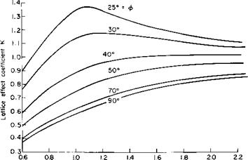
The lift coefficient of an airfoil in a cascade is not simply a function of its camber and angle of attack; it also depends on the geometry of the cascade, namely, the angle ф in Fig. 9-15 and the gap-chord ratio 2nr/BC.
Figure 9-16, taken from Ref. 4 (Fig. 1-9), presents the lattice effect coefficient K, the ratio of C, for an airfoil in a cascade to the C, produced by the same airfoil when acting by itself, as a function of ф and 2nr/BC. To clarify the use of К the value of C, for a flat-plate airfoil in cascade at an angle of attack, relative to Vx, of a theoretically would be
C, = 2nKot. (9-30)
An approximation to К was obtained in Ref. 6, which is in close agreement with the exact solution over a wide range of solidity and stagger angle ф. The closed-form approximation that follows approaches the exact solution for increasing values of 2nr/BC and is identical with the exact solution for ф-values of 0 and 90°.
С, _ 4r Г tan2 nX + tanh2 n Y 1
2rox BC sin ф tanh яУ(1 + tan2 nX) + cos ф tan nX( – tanh2 aT)J
where
= cos ф (Anr/BC)
![]() = sin ф (4tz r/BC)
= sin ф (4tz r/BC)
In lieu of correcting C, with the lattice effect coefficient, we can refer directly to tests of cascades of airfoil in order to obtain the desired turning of the flow. Such data can be obtained, for example, from Ref. 7.
In Ref. 4 a method, referred to as “the mean-streamline method,” is developed for calculating the shape of a blade section to give a desired pressure distribution. In this method the amount of turning to be produced by each section is related to the pressure difference required by that section. With this information, a mean-streamline and a section camber line that departs from it slightly can be determined. This method as well as additional considerations of cascades are presented in Chapter 11.


