Raising the critical Mach Number – sweepback
The second main way of raising the critical Mach Number (and this applies only to the wings, tail, fin and control surfaces) is sweepback – not just the few degrees of sweepback that was sometimes used, rather apologetically and for various and sometimes rather doubtful reasons, on subsonic aircraft, but 40°, 50°, 70° or more.
 |
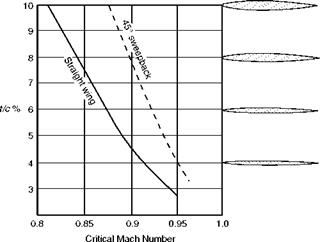
Fig 11.15 Critical Mach Number and t/c ratio
 |
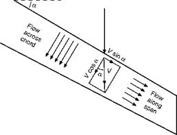
Sweepback of this magnitude not only delays the shock stall, but reduces its severity when it does occur. The theory behind this is that it is only the component of the velocity across the chord of the wing (V cos a) which is responsible for the pressure distribution and so for causing the shock wave (Fig. 11.16); the component У sin a along the span of the wing causes only frictional drag. This theory is borne out by the fact that when it does appear the shock wave lies parallel to the span of the wing, and only that part of the velocity perpendicular to the shock wave, i. e. across the chord, is reduced by the shock wave to subsonic speeds. As the figure clearly shows, the greater the sweepback the smaller will be the component of the velocity which is affected,
Fig 11.16 Sweepback – components of velocity
 |
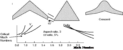
Fig 11.17 Effects of sweepback
Fig 11.18 Swept-back wings for transonic speeds and so the higher will be the critical Mach Number, and the less will be the drag at all transonic speeds of a wing of the same tic ratio and at the same angle of attack.
Experiment confirms the theoretical advantages of sweepback, though the improvement is not quite so great as the theory suggests. The dotted line in Fig. 11.15 shows how a wing swept back at 45° has a higher critical Mach Number than a straight wing at all values of tic ratio, the advantage being greater for the wings with the higher values of tic. Figure 11.17 tells us even more; it shows that sweepback not only increases the critical Mach Number, but it reduces the rate at which the drag coefficient rises (the slope of the curve), and it lowers the peak of the drag coefficient – and 45° of sweepback does all this better than 30°. Incidentally this figure also shows that, above about M = 2, sweepback has very little advantage – but that is another story and, in any case, aeroplanes cannot fly at M = 2 without first going through the transonic range.
Figure 11.18 shows various plan forms of swept-back wings.
Of course, as always, there are snags, and the heavily swept-back wing is no exception. There is tip stalling – an old problem, but a very important one; in the crescent-shaped wing (Fig. 11.18) an attempt has been made – with some success – to alleviate this by gradually reducing the sweepback from root to tip. CLmax is low, and therefore the stalling speed is high, and CLmax is obtained at too large an angle to be suitable for landing – another old
problem, and one that can generally be overcome by special slots, flaps or suction devices. There are also control problems of various kinds, and the designer doesn’t like the extra bending and twisting stresses that are inherent in the heavily swept-back wing design. But whatever the problems sweepback seems to have come to stay – at least for aircraft which are designed to fly for any length of time at transonic or low supersonic speeds.


