Rotor—Tail Rotor Interactions
The tail rotor has to operate in a relatively complex aerodynamic environment and must produce thrust with the relative flow coming from essentially any direction – see Newman (1994). For example, the tail rotor must operate properly in side winds and during yaw maneuvers. In a yawing maneuver, the tail rotor operates either in an effective climb or descent mode, depending on the yaw direction. The yawing direction that produces an effective descending condition is the most critical because it is possible for the tail rotor to enter into the vortex ring state (see Section 2.13.6). This can result in a loss of tail rotor authority and perhaps even a loss of control under certain conditions, a problem first explored by Amer & Gessow (1955). These effects are carefully examined during certification flight testing to ensure that there is a minimal chance that the helicopter will inadvertently exhibit undesirable flight characteristics.
As described previously in Section 6.9.4, the tail rotor is also mounted in proximity to a vertical fin or other empennage assembly and the resultant aerodynamic interactions will affect tail rotor operation. Furthermore, the operation of the tail rotor will be affected by turbulent separated flow generated by the main rotor hub and fuselage wakes, and also the energetic main rotor wake itself. This adverse environment means that the aerodynamic design requirements for the tail rotor are different in some respects from those of the main rotor. For these reasons, it is known to be difficult to design a tail rotor that will meet all aerodynamic, control, stability, weight, and structural requirements. See Lynn (1970), Cook (1978), В у ham (1990), and Newman (1994) for a detailed overview of tail rotor design issues.
The aerodynamic interactions between the main rotor and the tail rotor are discussed by Wiesner & Kohler (1973, 1974), Leverton et al. (1977), Balch (1984), Wilson (1990), Ellin (1993), Tarttelin & Martyn (1994), Coton et al. (2002), Early et al. (2002), and Wang et al. (2002). In forward flight there is a lateral asymmetry in dynamic pressure across the tail rotor, as with the main rotor, but the effects are alleviated by flapping hinges. Yet the tail rotor still trails its own unique wake, although this is much less powerful than the main rotor wake. The main rotor wake is known to roll up at its edges into a pair of “super-vortices,” this phenomenon having been alluded to several times previously in Chapter 10. This rollup effect produces a downwash over the tail rotor with a significant veiocity gradient in the iongitudinal direction. There is also an increased total pressure in the main rotor wake, which encroaches onto the tail rotor as forward flight speed builds.
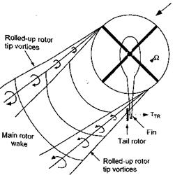
Of some importance in the aerodynamics and aeroacoustics of the tail rotor are the cutting or “chopping” types of interactions that take place as the tail rotor blades intersect the strong tip vortices trailed from the main rotor blades – see Leverton et al. (1977), Howe
(1989) , and Coton et al. (2002). Because the plane of rotation of the tail rotor is almost perpendicular to the main rotor (unless the tail rotor is canted), the plane of the tail rotor blades is essentially perpendicular to the vorticity vector of the tip vortices. The location of the interactions over the tail rotor disk are a function of several parameters, including the
Figure 11.26 The tail rotor may intersect and cut-through the strong tip vortices that are trailed from the main rotor.
flight condition (see Fig. 11.26). More interactions can usually be expected to occur when the helicopter is in higher speed forward flight or during descents.
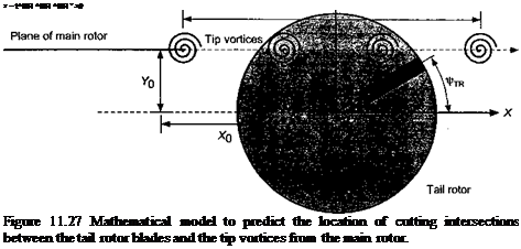
The number and location of the intersections between the tail rotor blades and the main rotor wake vortices can be determined using the same principles as those described in Section 10.4.2 for finding the main rotor BVI locations. In the first instance, a simple rigid wake model can be used to study the tail rotor interactions, such as that discussed by Newman (1994), but it must be recognized that considerable main rotor wake distortion can indeed be produced at the tail rotor. The geometry of this type of model is shown in Fig. 11.27. The tip vortices from the trailing edge of the main rotor disk are assumed to be convected at the free-stream velocity relative to the tail rotor and to be uninfluenced by the tail rotor.
 |
Yn
where і = 1, NbjR. The coordinates of a point on the axis of the tail rotor blades are given by
/ 2n{i – 1)
XTR = r cos UrTR———– ——— I Rtr, (11.9)
and
/ 2n(i — 1)
TTR = ±rsin UrTR———– ——— J Rtr, (11.10)
where the ± accounts for the direction of rotation of the tail rotor (counterclockwise or clockwise, respectively). The different rotational frequencies of the main and tail rotors means that the time scales are related by
= (1U1)
An intersection occurs when
are simultaneously satisfied. This solution can easily be found numerically.
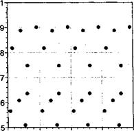
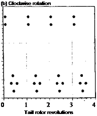
Representative results from this model (in terms of the radial intersection point as a function of tail rotor revolutions) are shown in Fig. 11.28 for a counterclockwise and for a clockwise turning tail rotor. Notice that the intersection pattern is periodic but differs considerably depending on the sense of rotation of the tail rotor, a point also noted by Leverton et al. (1977) and Newman (1994). This is because, in the case of a counterclockwise rotation, the tail rotor blades are advancing into the main rotor tip vortices whereas, for a clockwise rotation, the blades retreat away from the oncoming vortices. The implications are that minimizing the number of intersections will reduce unsteady airloads and tail rotor noise, and on this basis it appears that a clockwise rotation of the tail rotor (usually called rotation “aft at the top”) is the better choice, a result borne out by flight testing experience – seeEllin (1993).


![]()
![]()

 0.
0.
0.
0.
0.
0.
Wind over nose
![]()
![]()
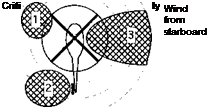 |
for loss of tail rotor effectiveness Zone 1: Effects of main rotor wake (port side).
Zone 2: Effects of main rotor wake (starboard side). Zone 3: Tail rotor may enter vortex ring state.
Figure 11.29 The impingement of the main rotor wake on the tail rotor can cause loss of tail rotor effectiveness. Adapted from Vuillet (1990) and other sources.
Clearly the aeroacoustics problem is relatively more complicated than this, but a parsimonious model like this illustrates one fundamental aspect of the tail rotor-main rotor wake interaction problem. The model can also be used to explore the effects of changing the phase angles between the tail rotor blades, such as the nonorthogonal set used on the AH-64 Apache (see Question 11.7). It should be pointed out, however, that the tail rotor was not designed for this way for acoustic purposes but instead to alleviate clearance issues with the pitch links.
The aerodynamic interactions between the main rotor and tail rotor in low-speed flight generally prove to be the most severe and the hardest to predict. Critical conditions include right and left crosswinds, where the bundled super-vortices trailed from the main rotor disk can impinge on the tail rotor. An example is shown in Fig. 11.29. Under these conditions the down wash and change in dynamic pressure across the tail rotor disk that is produced by the main rotor wake can degrade tail rotor performance. As previously mentioned, because of these effects, one normally finds that tail rotors that have an “aft at the top” rotation are preferable. This has been fotmd through flight testing to balance the aerodynamic forces and maintain good tail rotor authority over a wider range of flight conditions than the opposite sense of rotation. Other critical flight conditions include rearward flight near the ground or sideward flight to port – see Section 10.10.6. In rearward flight, the ground vortex can result m loss of tail rotor effectiveness. In sideward flight (or when hovering in a crosswind), the tail rotor operates in an effective descent and will eventually encounter the vortex ring state where a loss of anti-torque and yaw control effectiveness will occur. All of these issues are carefully examined during certification of the helicopter to ensure that there are no adverse effects or that potentially problem areas of the flight envelope can be fully identified.


