6.2.7.1 Vortex Lattice Methods
When the vortex lattice method is applied to wings, the surface is arbitrarily divided in the chordwise and spanwise directions into panels or boxes. Each panel contains a horseshoe vortex. The vortex-induced flow field for each panel is derived by the Biot-Savart
|
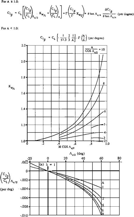
Figure 6.3 Example formula and charts from the USAF DATCOM. This covers only a small part of the material for calculation of the derivative C^ for straight-tapered wings. RAeS data sheets have similar functions and appearance. |
law. While this implies incompressible flow, the Prandtl-Glauert rule can extend the results to subcritical Mach numbers. The boundary condition of no flow across panels is fulfilled at just one control point per panel. Angle of attack and load distributions for the panels are found from a system of simultaneous linear equations that are easily solved on a digital computer. Distortions in data due to Reynolds’ number mismatches, jet boundary corrections, and model attachment problems in real wind tunnels are replaced with the necessary approximations of computational fluid dynamics.
When the panels lie in a flat plane and occupy constant percentage chord lines on an idealized straight-tapered wing at more or less arbitrary spanwise locations, and when each panel contains a line vortex across its local quarter chord point and trailing vortices along its side edges, whose collective vorticity provides tangential flow at every panel local three – quarter-chord point, the bound vorticity in each panel can be found by desktop methods, as in the Weissinger method. However, when panels or a mesh cover a complete airplane configuration, automatic machine computation methods become necessary. Depending on the method used, the computer defines the vortex strength for each panel.


