Aerodynamic Forces and Moments
At first glance, the generation of the aerodynamic force on a giant Boeing 747 may seem complex, especially in light of the complicated three-dimensional flow field over the wings, fuselage, engine nacelles, tail, etc. Similarly, the aerodynamic resistance on an automobile traveling at 55 mi/h on the highway involves a complex interaction of the body, the air, and the ground. However, in these and all other cases, the aerodynamic forces and moments on the body are due to only two basic sources:
1. Pressure distribution over the body surface
2. Shear stress distribution over the body surface
No matter how complex the body shape may be, the aerodynamic forces and moments on the body are due entirely to the above two basic sources. The only mechanisms nature has for communicating a force to a body moving through a fluid are pressure and shear stress distributions on the body surface. Both pressure p and shear stress r have dimensions of force per unit area (pounds per square foot or newtons per square meter). As sketched in Figure 1.8, p acts normal to the surface, and r acts tangential to the surface. Shear stress is due to the “tugging action” on the surface, which is caused by friction between the body and the air (and is studied in great detail in Chapters 15 to 20).
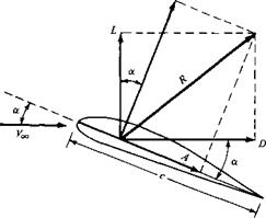
The net effect of the p and r distributions integrated over the complete body surface is a resultant aerodynamic force R and moment M on the body, as sketched in Figure 1.9. In turn, the resultant R can be split into components, two sets of which are shown in Figure 1.10. In Figure 1.10, V0c is the relative wind, defined as the
|
|
|
|
|
flow velocity far ahead of the body. The flow far away from the body is called the freestream, and hence is also called the freestream velocity. In Figure 1.10, by
definition,
L = lift = component of R perpendicular to Vx D = drag = component of R parallel to
The chord c is the linear distance from the leading edge to the trailing edge of the body. Sometimes, R is split into components perpendicular and parallel to the chord, as also shown in Figure 1.10. By definition,
N = normal force = component of R perpendicular to c A = axial force = component of R parallel to c
The angle of attack a is defined as the angle between c and Vx. Hence, a is also the angle between L and N and between D and A. The geometrical relation between these two sets of components is, from Figure 1.10,
L = N cos a — A sin a [1.1]
D = N sin a + A cos a [1.2]
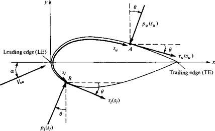
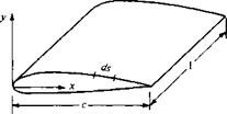
Let us examine in more detail the integration of the pressure and shear stress distributions to obtain the aerodynamic forces and moments. Consider the twodimensional body sketched in Figure 1.11. The chord line is drawn horizontally, and hence the relative wind is inclined relative to the horizontal by the angle of attack a. An xy coordinate system is oriented parallel and perpendicular, respectively, to the chord. The distance from the leading edge measured along the body surface to an arbitrary point A on the upper surface is su; similarly, the distance to an arbitrary point В on the lower surface is si. The pressure and shear stress on the upper surface are denoted by pu and ru, respectively; both pu and zu are functions of su. Similarly, Pi and Т/ are the corresponding quantities on the lower surface and are functions of
|
Figure 1.11 Nomenclature for the integration of pressure and shear stress distributions over a two-dimensional body surface. |
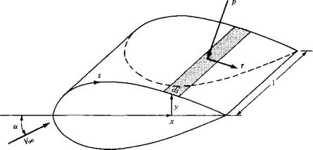
si. At a given point, the pressure is normal to the surface and is oriented at an angle 9 relative to the perpendicular; shear stress is tangential to the surface and is oriented at the same angle 9 relative to the horizontal. In Figure 1.11, the sign convention for в is positive when measured clockwise from the vertical line to the direction of p and from the horizontal line to the direction of r. In Figure 1.11, all thetas are shown in their positive direction. Now consider the two-dimensional shape in Figure 1.11 as a cross section of an infinitely long cylinder of uniform section. A unit span of such a cylinder is shown in Figure 1.12. Consider an elemental surface area dS of this cylinder, where dS — (ds)( ) as shown by the shaded area in Figure 1.12. We are interested in the contribution to the total normal force N’ and the total axial force A’ due to the pressure and shear stress on the elemental area dS. The primes on N’ and A’ denote force per unit span. Examining both Figures 1.11 and 1.12, we see that the elemental normal and axial forces acting on the elemental surface dS on the upper body surface are
dN’u — — pudsu cos0 — rudsu sin0 [1.3]
dA’u = —pudsu sin 9 + Tudsu cos 9 [1.4]
On the lower body surface, we have
dN{ = pidsi cos9 — Tidsisind [1.5]
dA = pidsi sin 9 + Tidsi cos 9 [1.6]
In Equations (1.3) to (1.6), the positive directions of N’ and A’ are those shown in Figure 1.10. In these equations, the positive clockwise convention for 9 must be followed. For example, consider again Figure 1.11. Near the leading edge of the body, where the slope of the upper body surface is positive, r is inclined upward, and hence it gives a positive contribution to N1. For an upward inclined г, в would
|
Figure 1.13 Aerodynamic force on an element of the body surface. |
be counterclockwise, hence negative. Therefore, in Equation (1.3), sin 0 would be negative, making the shear stress term (the last term) a positive value, as it should be in this instance. Hence, Equations (1.3) to (1.6) hold in general (for both the forward and rearward portions of the body) as long as the above sign convention for в is consistently applied.
 |
The total normal and axial forces per unit span are obtained by integrating Equations (1.3) to (1.6) from the leading edge (LE) to the trailing edge (ТЕ):
In turn, the total lift and drag per unit span can be obtained by inserting Equations (1.7) and (1.8) into (1.1) and (1.2); note that Equations (1.1) and (1.2) hold for forces on an arbitrarily shaped body (unprimed) and for the forces per unit span (primed).
The aerodynamic moment exerted on the body depends on the point about which moments are taken. Consider moments taken about the leading edge. By convention, moments which tend to increase a (pitch up) are positive, and moments which tend to decrease a (pitch down) are negative. This convention is illustrated in Figure 1.13. Returning again to Figures 1.11 and 1.12, the moment per unit span about the leading edge due to p and г on the elemental area dS on the upper surface is
dM’u = (pu cos в + zu sin0)x dsu + (—pu sin# + xu cos 9)y dsu [1.9] On the bottom surface,
dM[ = {—pi cos в + tі sin 0)x dsi + (pi sin в + Т/ cosd)y dsi [1.10]
In Equations (1.9) and (1.10), note that the same sign convention for в applies as before and that у is a positive number above the chord and a negative number below the chord. Integrating Equations (1.9) and (1.10) from the leading to the trailing edges, we obtain for the moment about the leading edge per unit span
/■ТЕ
+ / [(—р/ cos в + n sin в)х + (pi sin в + Ті cos в)у] dsi
J LE
|
|
||
|

In Equations (1.7), (1.8), and (1.11), 9, x, and у are known functions of і for a given body shape. Hence, if pu, pi, t„, and г/ are known as functions of і (from theory or experiment), the integrals in these equations can be evaluated. Clearly, Equations (1.7), (1.8), and (1.11) demonstrate the principle stated earlier, namely, the sources of the aerodynamic lift, drag, and moments on a body are the pressure and shear stress distributions integrated over the body. A major goal of theoretical aerodynamics is to calculate p{s) and г(.v) for a given body shape and freestream conditions, thus yielding the aerodynamic forces and moments via Equations (1.7), (1.8), and (1.11).
As our discussions of aerodynamics progress, it will become clear that there are quantities of an even more fundamental nature than the aerodynamic forces and moments themselves. These are dimensionless force and moment coefficients, defined as follows. Let poo and be the density and velocity, respectively, in the freestream, far ahead of the body. We define a dimensional quantity called the freestream dynamic pressure as
Dynamic pressure: qx = ^p^V^
The dynamic pressure has the units of pressure (i. e., pounds per square foot or newtons per square meter). In addition, let S be a reference area and l be a reference length. The dimensionless force and moment coefficients are defined as follows:
 L
L
ЯоqS
QooS N
Cn =——–
qooS
_ A
Ca q<*>s
_ M
CM=q^Sl
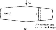
In the above coefficients, the reference area S and reference length l are chosen to pertain to the given geometric body shape; for different shapes, S and l may be different things. For example, for an airplane wing, S is the planform area, and l is the mean chord length, as illustrated in Figure 1.14a. However, for a sphere, S is the cross-sectional area, and l is the diameter, as shown in Figure 1.14b. The particular choice of reference area and length is not critical; however, when using force and moment coefficient data, you must always know what reference quantities the particular data are based upon.
The symbols in capital letters listed above, i. e., CL, CD, Cm, and CA, denote the force and moment coefficients for a complete three-dimensional body such as an airplane or a finite wing. In contrast, for a two-dimensional body, such as given in Figures 1.11 and 1.12, the forces and moments are per unit span. For these two-
|
|
Цс f c *1 nd2
її j (l j S – cross-sectional area =
( j 1 = d = diameter
(b)
Figure 1.14 Some reference areas and lengths.
dimensional bodies, it is conventional to denote the aerodynamic coefficients by lowercase letters; e. g.,
_ L’ _ D’ _ M’
qooC qooC m qooC2
where the reference area S = c(l) = c.
Two additional dimensionless quantities of immediate use are
Pressure coefficient: C„ = ——^
*700 r
Skin friction coefficient: c t = —
qoo
where poo is the freestream pressure.
The most useful forms of Equations (1.7), (1.8), and (1.11) are in terms of the dimensionless coefficients introduced above. From the geometry shown in Figure 1.15,
dx = dx cos в [1.12]
dy = — (ds sin#) [1.13]
S — c(l) [1.14]
Substituting Equations (1.12) and (1.13) into Equations (1.7), (1.8), and (1.11), dividing by qoo, and further dividing by S in the form of Equation (1.14), we obtain the following integral forms for the force and moment coefficients:
![]()
|
|
|
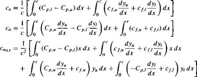
The simple algebraic steps are left as an exercise for the reader. When evaluating these integrals, keep in mind that yu is directed above the x axis, and hence is positive, whereas yi is directed below the x axis, and hence is negative. Also, dy/dx on both the upper and lower surfaces follow the usual rule from calculus, i. e., positive for those portions of the body with a positive slope and negative for those portions with a negative slope.
The lift and drag coefficients can be obtained from Equations (1.1) and (1.2) cast in coefficient form:
q = cn cos a — ca sin a [1.18]
Cd — cn sin a + ca cos a [1.19]
Integral forms for c; and cj are obtained by substituting Equations (1.15) and (1.16) into (1.18) and (1.19).
It is important to note from Equations (1.15) through (1.19) that the aerodynamic force and moment coefficients can be obtained by integrating the pressure and skin friction coefficients over the body. This is a common procedure in both theoretical and experimental aerodynamics. In addition, although our derivations have used a two-dimensional body, an analogous development can be presented for
three-dimensional bodies—the geometry and equations only get more complex and involved—the principle is the same.
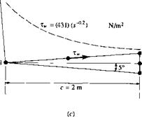
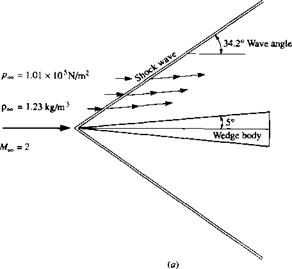
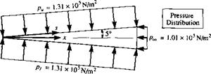
![]() Consider the supersonic flow over a 5° half-angle wedge at zero angle of attack, as sketched in Figure 1.16a. The freestream Mach number ahead of the wedge is 2.0, and the freestream pressure and density are 1.01 x 10⁵ N/m2 and 1.23 kg/m3, respectively (this corresponds to standard sea level conditions). The pressures on the upper and lower surfaces of the wedge are constant with distance s and equal to each other, namely, p„ = pi = 1.31 x 10s N/m2, as shown in Figure 1.16b. The pressure exerted on the base of the wedge is equal to px. As seen in Figure 1.16c, the shear stress varies over both the upper and lower surfaces as r„, =431 s 2. The chord length, c, of the wedge is 2 m. Calculate the drag coefficient for the wedge.
Consider the supersonic flow over a 5° half-angle wedge at zero angle of attack, as sketched in Figure 1.16a. The freestream Mach number ahead of the wedge is 2.0, and the freestream pressure and density are 1.01 x 10⁵ N/m2 and 1.23 kg/m3, respectively (this corresponds to standard sea level conditions). The pressures on the upper and lower surfaces of the wedge are constant with distance s and equal to each other, namely, p„ = pi = 1.31 x 10s N/m2, as shown in Figure 1.16b. The pressure exerted on the base of the wedge is equal to px. As seen in Figure 1.16c, the shear stress varies over both the upper and lower surfaces as r„, =431 s 2. The chord length, c, of the wedge is 2 m. Calculate the drag coefficient for the wedge.
Solution
We will carry out this calculation in two equivalent ways. First, we calculate the drag from Equation (1.8), and then obtain the drag coefficient. In turn, as an illustration of an alternate approach, we convert the pressure and shear stress to pressure coefficient and skin friction coefficient, and then use Equation (1.16) to obtain the drag coefficient.
Since the wedge in Figure 1.16 is at zero angle of attach, then D’ = A’. Thus, the drag can be obtained from Equation (1.8) as
/>[’[■ pTE
D’ = ( —p„sin0 + T„COS0)c/.V„ + (Pi Sind + T/COS0)^.V/
Jle Jle
Referring to Figure 1.16c, recalling the sign convention for в, and noting that integration over the upper surface goes from. q to s2 on the inclined surface and from s2 to + on the base, whereas integration over the bottom surface goes from я to v4 on the inclined surface and from s4 to л’з on the base, we find that the above integrals become
f — pu sin в dsu = ( —(1.31 x 10⁵)sin(—5“)z2.v„
JLE Js і
+ j —(1.01 x 10⁵) sin 90° dsu
= 1.142 x 10⁴(,v2 – .я) – 1.01 x 10⁵(+ – s2)
= 1.142 x 10⁴ (—!—) – 1.01 x 10⁵(c)(tan 5°)
Vcos5°/
= 1.142 x 10⁴(2.008) – 1.01 x 10s(0.175) = 5260 N
Г ТЕ p. У4 p S}
pisinedsi = (1.31 x 10s)sin(5°)ds,+ (1.01 x 10⁵) sin(-90°)dst
JLE Js i */.s-4
= 1.142 x 10⁴(.v4 — я) +1.01 x 10⁵(—l)(.v3 – 44)
= 1.142 x 10⁴ (——) – 1.01 x 10⁵(c)(tan 5°)
Vcos5°z
= 2.293 x 10⁴ – 1.767 x 104 = 5260 N
|
|
|
|
Note that the integrals of the pressure over the top and bottom surfaces, respectively, yield the same contribution to the drag—a result to be expected from the symmetry of the configuration in Figure 1.16:
Г ТЕ rs2
r„cos в dsu = I 431s~02cos(—5°)dsu J LE Л,
![]() / C Vі.
/ C Vі.
= 429 (——– ) — = 936.5 N
Vcos5°/ 0.8
 r/cos0dsi = I 43b °-2cos(—5°)ds.
![]() 4′ ~si
4′ ~si
0. 8
/ c y1» 1
= 429 (—– -) — = 936.5 N
Vcos5°/ 0.8
Again, it is no surprise that the shear stress acting over the upper and lower surfaces, respectively, give equal contributions to the drag; this is to be expected due to the symmetry of the wedge shown in Figure 1.16. Adding the pressure integrals, and then adding the shear stress integrals, we have for total drag
![]() D’ = 1.052 x 10⁴ + 0.1873 x 104 =
D’ = 1.052 x 10⁴ + 0.1873 x 104 =
4——- v — 1 v ‘ 11 "
pressure skin friction
drag drag
Note that, for this rather slender body, but at a supersonic speed, most of the drag is pressure drag. Referring to Figure 1.16a, we see that this is due to the presence of an oblique shock wave from the nose of the body, which acts to create pressure drag (sometimes called “wave drag”). In this example, only 15 percent of the drag is skin friction drag; the other 85 percent is the pressure drag (wave drag). This is typical of the drag of slender supersonic bodies. In contrast, as we will see later, the drag of a slender body at subsonic speed, where there is no shock wave, is mainly skin friction drag.
The drag coefficient is obtained as follows. The velocity of the freestream is twice the sonic speed, which is given by
«СС = Vyrt*c = v/(l-4)(287)(288) = 340.2 m/s
(See Chapter 8 for a derivation of this expression for the speed of sound.) Note that, in the above, the standard sea level temperature of 288 К is used. Hence, V^ = 2(340.2) = 680.4 m/s. Thus,
qx = IpxV^ = (0.5)(1.23)(680.4)2 = 2.847 x 10⁵ N/m2 Also, S = c(l) = 2.0m2
An alternate solution to this problem is to use Equation (1.16), integrating the pressure coefficients and skin friction coefficients to obtain directly the drag coefficient. We proceed as follows:
![]()
|
|
On the lower surface, we have the same value for C„, i. e.,
■■ 0.1054
 |
Also,
= 0.009223x I2 +0.00189x°’8|p
![]() = 0.01854 + 0.00329 :
= 0.01854 + 0.00329 :
This is the same result as obtained earlier.
Example 1 .2 | Consider a cone at zero angle of attack in a hypersonic flow. (Hypersonic flow is very highspeed flow, generally defined as any flow above a Mach number of 5; hypersonic flow is further defined in Section 1.10.) The half-angle of the cone is вс, as shown in Figure 1.17. An approximate expression for the pressure coefficient on the surface of a hypersonic body is given by the newtonian sine-squared law (to be derived in Chapter 14):
Cp = 2 sin2 вс
Note that Cp, hence, p; is constant along the inclined surface of the cone. Along the base of the body, we assume that p = px. Neglecting the effect of friction, obtain an expression for the drag coefficient of the cone, where Co is based on the area of the base St,.
Solution
We cannot use Equations (1.15) to (1.17) here. These equations are expressed for a twodimensional body, such as the airfoil shown in Figure 1.15, whereas the cone in Figure 1.17 is a shape in three-dimensional space. Hence, we must treat this three-dimensional body as follows. From Figure 1.17, the drag force on the shaded strip of surface area is
(p sin6>c.)(2jrг)- =2nrpdr
sin вс
![]()
|
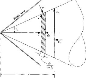
The total drag due to the pressure acting over the total surface area of the cone is
rrb rn>
D= І Inrpdr — I Ілр-^dr
Jo Jo
The first integral is the horizontal force on the inclined surface of the cone, and the second integral is the force on the base of the cone. Combining the integrals, we have
D=f 2лг(р – PoJr/r = 7T(p – px)rl Jo
Referenced to the base area, nrft, the drag coefficient is
![]()
![]() D ЛГЬІР ~ Poo)
D ЛГЬІР ~ Poo)
(Note: The drag coefficient for a cone is equal to its surface pressure coefficient.) Flence, using the newtonian sine-squared law, we obtain


