Angular Velocity, Vorticity, and Strain
In several of our previous discussions, we made use of the concept of a fluid element moving through the flow field. In this section, we examine this motion more closely, paying particular attention to the orientation of the element and its change in shape as it moves along a streamline. In the process, we introduce the concept of vorticity, one of the most powerful quantities in theoretical aerodynamics.
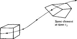
Consider an infinitesimal fluid element moving in a flow field. As it translates along a streamline, it may also rotate, and in addition its shape may become distorted as sketched in Figure 2.30. The amount of rotation and distortion depends on the velocity field; the purpose of this section is to quantify this dependency.
|
streamline is a combination of translation and rotation; in addition, the shape of the element can become distorted.
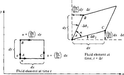
Consider a two-dimensional flow in the xy plane. Also, consider an infinitesimal fluid element in this flow. Assume that at time t the shape of this fluid element is rectangular, as shown at the left of Figure 2.31. Assume that the fluid element is moving upward and to the right; its position and shape at time t + At are shown at the right in Figure 2.31. Note that during the time increment At, the sides AB and AC have rotated through the angular displacements — Дві and Аві, respectively. (Counterclockwise rotations by convention are considered positive; since line A В is shown with a clockwise rotation in Figure 2.31, the angular displacement is negative, — Дві.) At present, consider just the line AC. It has rotated because during the time increment At, point C has moved differently from point A. Consider the velocity in the у direction. At point A at time t, this velocity is v, as shown in Figure 2.31. Point C is a distance dx from point A; hence, at time t the vertical component of velocity of point C is given by v + (dv/dx) dx. Hence,
Distance in у direction that A moves
= vAt
during time increment At

Distance in у direction that C moves
This net displacement is shown at the right of Figure 2.31. From the geometry of Figure 2.31,
![]()
![]() [2.119]
[2.119]
|
Since A92 is a small angle, tan A92 ~ A92. Hence, Equation (2.119) reduces to
Now consider line AB. The x component of the velocity at point A at time t is u, as shown in Figure 2.31. Because point В is a distance dy from point A, the horizontal component of velocity of point В at time t is и + (du/dy)dy. By reasoning similar to that above, the net displacement in the x direction of В relative to A over the time increment At is [(du/dy) dy] At, as shown in Figure 2.31. Hence,
 |
|
|
|
|
|
|
|
|
|
|
|
|
|
|
|
By definition, the angular velocity of the fluid element as seen in the xy plane is the average of the angular velocities of lines AB and AC. Let a>z denote this angular velocity. Therefore, by definition,
Combining Equations (2.123) to (2.125) yields
1 ![]() /Эи Эи
/Эи Эи
z 2 Эх ду
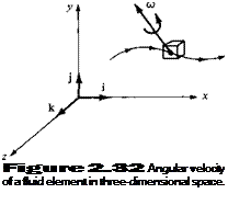
In the above discussion, we have considered motion in the xy plane only. However, the fluid element is generally moving in three-dimensional space, and its angular velocity is a vector ш that is oriented in some general direction, as shown in Figure 2.32. In Equation (2.126), we have obtained only the component of ш in the z direction; this explains the subscript z in Equations (2.125) and (2.126). The x and у components of <о can be obtained in a similar fashion. The resulting angular velocity of the fluid element in three-dimensional space is
Equation (2.127) is the desired result; it expresses the angular velocity of the fluid element in terms of the velocity field, or more precisely, in terms of derivatives of the velocity field.
The angular velocity of a fluid element plays an important role in theoretical aerodynamics, as we shall soon see. However, the expression 2со appears frequently, and therefore we define a new quantity, vorticity, which is simply twice the angular velocity. Denote vorticity by the vector |:
 |
£ = 2<u
Hence, from Equation (2.127),
Recall Equation (2.22) for V x V in cartesian coordinates. Since u, v, and w denote the x, y, and z components of velocity, respectively, note that the right sides of Equations (2.22) and (2.128) are identical. Hence, we have the important result that
 [2.129]
In a velocity field, the curl of the velocity is equal to the vorticity.
The above leads to two important definitions:
1. If V x V ф 0 at every point in a flow, the flow is called rotational. This implies that the fluid elements have a finite angular velocity.
2. If V x V = 0 at every point in a flow, the flow is called irrotational. This implies that the fluid elements have no angular velocity; rather, their motion through space is a pure translation.
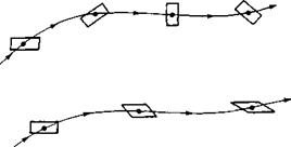
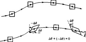
The case of rotational flow is illustrated in Figure 2.33. Here, fluid elements moving along two different streamlines are shown in various modes of rotation. In contrast, the case of irrotational flow is illustrated in Figure 2.34. Here, the upper streamline shows a fluid element where the angular velocities of its sides are zero. The lower streamline shows a fluid element where the angular velocities of two intersecting sides are finite but equal and opposite to each other, and so their sum is identically zero. In both cases, the angular velocity of the fluid element is zero; i. e., the flow is irrotational.
If the flow is two-dimensional (say, in the xy plane), then from Equation (2.128),
![]()
![]() [2.130]
[2.130]
![]()
|
|
Also, if the flow is irrotational, £ = 0. Hence, from Equation (2.130),
![Angular Velocity, Vorticity, and Strain Подпись: [2.131]](/img/3128/image331.gif) dv 3 и dx dy
dv 3 и dx dy
Equation (2.131) is the condition of irrotationality for two-dimensional flow. We will have frequent occasion to use Equation (2.131).
Why is it so important to make a distinction between rotational and irrotational flows? The answer becomes blatantly obvious as we progress in our study of aerodynamics; we find that irrotational flows are much easier to analyze than rotational flows. However, irrotational flow may at first glance appear to be so special that its applications are limited. Amazingly enough, such is not the case. There are a large number of practical aerodynamic problems where the flow field is essentially irrotational, e. g., the subsonic flow over airfoils, the supersonic flow over slender bodies at small angle of attack, and the subsonic-supersonic flow through nozzles. For such cases, there is generally a thin boundary layer of viscous flow immediately adjacent to the surface; in this viscous region the flow is highly rotational. However, outside this boundary layer, the flow is frequently irrotational. As a result, the study of irrotational flow is an important aspect of aerodynamics.
Return to the fluid element shown in Figure 2.31. Let the angle between sides A В and AC be denoted by к. As the fluid element moves through the flow field, к will change. In Figure 2.31, at time t, к is initially 90°. At time t + At, к has changed by the amount А к, where
![]() А к = – Д02 – (-Д0О
А к = – Д02 – (-Д0О
By definition, the strain of the fluid element as seen in the xy plane is the change in к, where positive strain corresponds to a decreasing к. Hence, from Equation (2.132),
Strain = —Лк = Л02 — A#i [2.133]
In viscous flows (to be discussed in Chapters 15 to 20), the time rate of strain is an important quantity. Denote the time rate of strain by єху, where in conjunction with
|
" 3 и |
du |
du |
|
dx |
dy |
3z |
|
dv |
dv |
dv |
|
dx |
dy |
dz |
|
dw |
dw |
dw |
|
_ dx |
dy |
~dz |
The sum of the diagonal terms is simply equal to V • V, which from Section 2.3 is equal to the time rate of change of volume of a fluid element; hence, the diagonal terms represent the dilatation of a fluid element. The off-diagonal terms are cross derivatives which appear in Equations (2.127), (2.128), and (2.135a to c). Hence, the off-diagonal terms are associated with rotation and strain of a fluid element.
In summary, in this section, we have examined the rotation and deformation of a fluid element moving in a flow field. The angular velocity of a fluid element and the corresponding vorticity at a point in the flow are concepts which are useful in the analysis of both inviscid and viscous flows; in particular, the absence of vorticity— irrotational flow—greatly simplifies the analysis of the flow, as we will see. We take advantage of this simplification in much of our treatment of inviscid flows in subsequent chapters. On the other hand, we do not make use of the time rate of strain until we discuss viscous flow, beginning with Chapter 15.
|
|
||
|
|||
|
|||
|
|||
|
|||
|
|||
|
|||
|
|||
|
|||
|
|||
|
|||
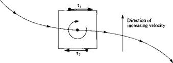
In Example 2.5, we demonstrated a basic result which holds in general for viscous flows, namely, viscous flows are rotational. This is almost intuitive. For example, consider an infinitesimally small fluid element moving along a streamline, as sketched in Figure 2.35. If this is a viscous flow, and assuming that the velocity increases in the upward direction (i. e., the velocity is higher on the neighboring streamline above and lower on the neighboring streamline below), then the shear stresses on the upper and lower faces of the fluid element will be in the directions shown. Such shear stresses will be discussed at length in Chapter 15. Examining Figure 2.35, we see clearly that the shear stresses exert a rotational moment about the center of the element, thus providing a mechanism for setting the fluid element into rotation. Although this picture is overly simplistic, it serves to emphasize that viscous flows are rotational flows. On the other hand, as stated earlier in this section, there are numerous

|
inviscid flow problems that are irrotational, with the attendant simplifications to be explained later. Some inviscid flows are rotational, but there exists such a large number of practical aerodynamic problems described by inviscid, irrotational flows that the distinction between rotational and irrotational flow is an important consideration.


