Applied Aerodynamics: The Aerodynamic Coefficients—Their Magnitudes and Variations
With the present section, we begin a series of special sections in this book under the general heading of “applied aerodynamics.” The main thrust of this book is to present the fundamentals of aerodynamics, as is reflected in the book’s title. However, applications of these fundamentals are liberally sprinkled throughout the book, in the text material, in the worked examples, and in the homework problems. The term applied aerodynamics normally implies the application of aerodynamics to the practical evaluation of the aerodynamic characteristics of real configurations such as airplanes, missiles, and space vehicles moving through an atmosphere (the earth’s, or that of another planet). Therefore, to enhance the reader’s appreciation of such applications, sections on applied aerodynamics will appear near the end of many of the chapters. To be specific, in this section, we address the matter of the aerodynamic coefficients defined in Section 1.5; in particular, we focus on lift, drag, and moment coefficients. These nondimensional coefficients are the primary language of applications in external aerodynamics (the distinction between external and internal aerodynamics was made in Section 1.2). It is important for you to obtain a feeling for
typical values of the aerodynamic coefficients. (For example, do you expect a drag coefficient to be as low as 10 5, or maybe as high as 1000—does this make sense?) The purpose of this section is to begin to provide you with such a feeling, at least for some common aerodynamic body shapes. As you progress through the remainder of this book, make every effort to note the typical magnitudes of the aerodynamic coefficients that are discussed in various sections. Having a realistic feel for these magnitudes is part of your technical maturity.
Question: What are some typical drag coefficients for various aerodynamic configurations? Some basic values are shown in Figure 1.39. The dimensional analysis described in Section 1.7 proved that Co — /(M, Re). In Figure 1.39, the drag – coefficient values are for low speeds, essentially incompressible flow; therefore, the Mach number does not come into the picture. (For all practical purposes, for an incompressible flow, the Mach number is theoretically zero, not because the velocity goes to zero, but rather because the speed of sound is infinitely large. This will be made clear in Section 8.3.) Thus, for a low-speed flow, the aerodynamic coefficients
|
|
|
|
|
|
|
|
|
|
|

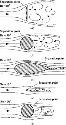
for a fixed shape at a fixed orientation to the flow are functions of just the Reynolds number. In Figure 1.39, the Reynolds numbers are listed at the left and the drag – coefficient values at the right. In Figure 1.39a, a flat plate is oriented perpendicular to the flow; this configuration produces the largest possible drag coefficient of any conventional configuration, namely, Co = D’/q^S = 2.0, where. S’ is the frontal area per unit span, i. e., S = (d)(1), where d is the height of the plate. The Reynolds number is based on the height d i. e., Re = рж V^d//i^ = 105. Figure 1.39b illustrates flow over a circular cylinder of diameter d; here, Co = 1.2, considerably smaller than the vertical plate value in Figure 1.39a. The drag coefficient can be reduced dramatically by streamlining the body, as shown in Figure 1.39c. Flere, Co = 0.12; this is an order of magnitude smaller than the circular cylinder in Figure 1.39£>. The Reynolds numbers for Figure 1.39a, b, and c are all the same value, based on d (diameter). The drag coefficients are all defined the same, based on a reference area per unit span of (d)(1). Note that the flow fields over the configurations in Figure 1.39a, b, and c show a wake downstream of the body; the wake is caused by the flow separating from the body surface, with a low-energy, recirculating flow inside the wake. The phenomenon of flow separation will be discussed in detail in Part 4 of this book, dealing with viscous flows. Flowever, it is clear that the wakes diminish in size as we progressively go from Figure 1.39a, b, and c. The fact that CD also diminishes progressively from Figure 1.39a, b, and c is no accident—it is a direct result of the regions of separated flow becoming progressively smaller. Why is this so? Simply consider this as one of the many interesting questions in aerodynamics—a question that will be answered in due time in this book. Note, in particular that the physical effect of the streamlining in Figure 1.39c results in a very small wake, hence a small value for the drag coefficient.
Consider Figure 1.39d, where once again a circular cylinder is shown, but of much smaller diameter. Since the diameter here is 0. Id, the Reynolds number is now 104 (based on the same freestream Too, px, and /i^ as Figure 1.39a, b, and c). It will be shown in Chapter 3 that Co for a circular cylinder is relatively independent of Re between Re = 104 and 105. Since the body shape is the same between Figure 1.39c/ and b, namely, a circular cylinder, then Co is the same value of 1.2 as shown in the figure. Flowever, since the drag is given by D’ = qxSCo, and S is one-tenth smaller in Figure 1.39 d, then the drag force on the small cylinder in Figure 139 d is one-tenth smaller than that in Figure 1.39b.
Another comparison is illustrated in Figure 1.39c and d. Here we are comparing a large streamlined body of thickness d with a small circular cylinder of diameter
O. ld. For the large streamlined body in Figure 1.39c,
D’ = qooSCo = 0.12 q^d
For the small circular cylinder in Figure 1.39d,
D’ = qooSCD — qoo(0.d)(.2) — O. Hq^d
The drag values are the same! Thus, Figure 1.3c and d illustrate that the drag on a circular cylinder is the same as that on the streamlined body which is ten times thicker—another way of stating the aerodynamic value of streamlining.
As a final note in regard to Figure 1.39, the flow over a circular cylinder is again shown in Figure 1.39c. However, now the Reynolds number has been increased to 107, and the cylinder drag coefficient has decreased to 0.6—a dramatic factor of two less than in Figure 139b and d. Why has Co decreased so precipitously at the higher Reynolds number? The answer must somehow be connected with the smaller wake behind the cylinder in Figure 1.39e compared to Figure 1.39b. What is going on here? This is one of the fascinating questions we will answer as we progress through our discussions of aerodynamics in this book—an answer that will begin with Section 3.18 and culminate in Part 4 dealing with viscous flow.
At this stage, pause for a moment and note the values of Co for the aerodynamic shapes in Figure 1.39. With Co based on the frontal projected area (S = <i(l) per unit span), the values of Cd range from a maximum of 2 to numbers as low as 0.12. These are typical values of Co for aerodynamic bodies.
Also, note the values of Reynolds number given in Figure 1.39. Consider a circular cylinder of diameter 1 m in a flow at standard sea level conditions = 1.23 kg/m3 and р. ж = 1.789 x 10⁻⁵ kg/m • s) with a velocity of 45 m/s (close to 100 mi/h). For this case,
Note that the Reynolds number is over 3 million; values of Re in the millions are typical of practical applications in aerodynamics. Therefore, the large numbers given for Re in Figure 1.39 are appropriate.
 |
|
Let us examine more closely the nature of the drag exerted on the various bodies in Figure 1.39. Since these bodies are at zero angle of attack, the drag is equal to the axial force. Hence, from Equation (1.8) the drag per unit span can be written as
рТЕ a ТЕ
I rM cos 9dsu– I ti cos 0 ds/
JLE JLE
skin friction drag
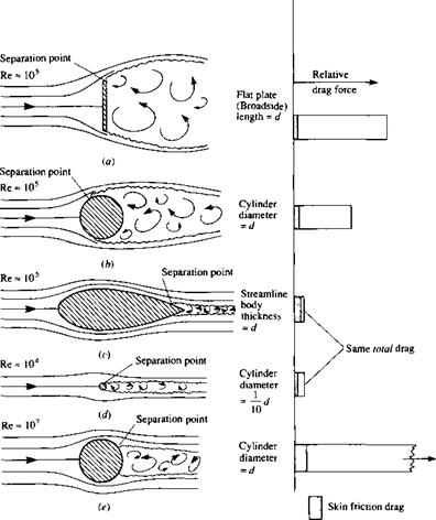
That is, the drag on any aerodynamic body is composed of pressure drag and skin friction drag; this is totally consistent with our discussion in Section 1.5, where it is emphasized that the only two basic sources of aerodynamic force on a body are the pressure and shear stress distributions exerted on the body surface. The division of total drag onto its components of pressure and skin friction drag is frequently useful in analyzing aerodynamic phenomena. For example, Figure 1.40 illustrates the comparison of skin friction drag and pressure drag for the cases shown in Figure 1.39. In Figure 1.40, the bar charts at the right of the figure give the relative drag force on each body; the cross-hatched region denotes the amount of skin friction drag, and the blank region is the amount of pressure drag. The freestream density and viscosity are the same for Figure 1.40a to e; however, the freestream velocity Vx is varied by
![]()
|
|
|
|
|

□
the necessary amount to achieve the Reynolds numbers shown. That is, comparing Figure 1.40b and e, the value of is much larger for Figure 1.40c. Since the drag force is given by
D’ = PoovlscD
then the drag for Figure 1,40c is much larger than for Figure 1.40b. Also shown in the bar chart is the equal drag between the streamlined body of thickness d and
the circular cylinder of diameter 0. Id—a comparison discussed earlier in conjunction with Figure 1.39. Of most importance in Figure 1.40, however, is the relative amounts of skin friction and pressure drag for each body. Note that the drag of the vertical flat plate and the circular cylinders is dominated by pressure drag, whereas, in contrast, most of the drag of the streamlined body is due to skin friction. Indeed, this type of comparison leads to the definition of two generic body shapes in aerodynamics, as follows:
Blunt body = a body where most of the drag is pressure drag Streamlined body = a body where most of the drag is skin friction drag
In Figures 1.39 and 1.40, the vertical flat plate and the circular cylinder are clearly blunt bodies.
The large pressure drag of blunt bodies is due to the massive regions of flow separation which can be seen in Figures 1.39 and 1.40. The reason why flow separation causes drag will become clear as we progress through our subsequent discussions. Hence, the pressure drag shown in Figure 1.40 is more precisely denoted as “pressure drag due to flow separation”; this drag is frequently called form drag. (For an elementary discussion of form drag and its physical nature, see Reference 2.)
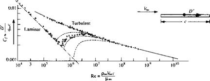
Let us now examine the drag on a flat plate at zero angle of attack, as sketched in Figure 1.41. Here, the drag is completely due to shear stress; there is no pressure force in the drag direction. The skin friction drag coefficient is defined as
D’ D’
Cf =——— =————-
4oo$ 9ooC(l)
where the reference area is the planform area per unit span, i. e., the surface area as seen by looking down on the plate from above. C/ will be discussed further in Chapter 16. However, the purpose of Figure 1.41 is to demonstrate that:
|
Figure 1.41 Variation of laminar and turbulent skin friction coefficient for a flat plate as a function of Reynolds number based on the chord length of the plate. The intermediate dashed curves are associated with various transition paths from laminar flow to turbulent flow. |
1. Cf is a strong function of Re, where Re is based on the chord length of the plate, Re = PooVooc/^oo – Note that C/ decreases as Re increases.
2. The value of Cf depends on whether the flow over the plate surface is laminar or turbulent, with the turbulent C/ being higher than the laminar Cf at the same Re. What is going on here? What is laminar flow? What is turbulent flow? Why does it affect Cfl The answers to these questions will be addressed in Chapters 15, 17, and 18.
3. The magnitudes of Cf range typically from 0.001 to 0.01 over a large range of Re. These numbers are considerably smaller than the drag coefficients listed in Figure 1.39. This is mainly due to the different reference areas used. In Figure 1.39, the reference area is a cross-sectional area normal to the flow; in Figure 1.41, the reference area is the planform area.
A flat plate is not a very practical aerodynamic body—it simply has no volume. Let us now consider a body with thickness, namely, an airfoil section. An NACA 63-210 airfoil section is one such example. The variation of the drag coefficient, cj, with angie of attack is shown in Figure і.42. Here, as usual, cj is defined as
D’
Cd – ———-
*?ooC
where D’ is the drag per unit span. Note that the lowest value of cd is about 0.0045. The NACA 63-210 airfoil is classified as a “iaminar-flow airfoil” because it is designed to promote such a flow at small a. This is the reason for the “bucketlike” appearance of the Cd curve at low a; at higher a, transition to turbulent flow occurs over the airfoil
0.02 – 0.016 –
 cd 0.012 – 0.008 – 0.004 –
-1.2 -0.8 -0.4 0 0.4 0.8 1.2
ci
______ I______ I I I I
-8 -4 0 4 8
a, degrees
Figure 1.42 Variation of section drag coefficient for an NACA 63-210 airfoil. Re = 3 x 10⁶.
surface, causing a sharp increase in cd. Hence, the value of cd = 0.0045 occurs in a laminar flow. Note that the Reynolds number is 3 million. Once again, a reminder is given that the various aspects of laminar and turbulent flows will be discussed in Part
4. The main point here is to demonstrate that typical airfoil drag-coefficient values are on the order of 0.004 to 0.006. As in the case of the streamlined body in Figures 1.39 and 1.40, most of this drag is due to skin friction. However, at higher values of a, flow separation over the top surface of the airfoil begins to appear and pressure drag due to flow separation (form drag) begins to increase. This is why cd increases with increasing a in Figure 1.42.
Let us now consider a complete airplane. In Chapter 3, Figure 3.2 is a photograph of the Seversky P-35, a typical fighter aircraft of the late 1930s. Figure 1.43 is a detailed drag breakdown for this type of aircraft. Configuration 1 in Figure 1.43 is the stripped-down, aerodynamically cleanest version of this aircraft; its drag coefficient (measured at an angle of attack corresponding to a lift coefficient of CL = 0.15) is
|
Condition |
CD |
ACo |
ACd, |
|
|
number |
Description |
(Cl= 0.15) |
%a |
|
|
1 |
Completely faired condition, long nose fairing |
0.0166 |
||
|
2 |
Completely faired condition, blunt nose fairing |
0.0169 |
||
|
3 |
Original cowling added, no airflow through cowling |
0.0186 |
0.0020 |
12.0 |
|
4 |
Landing-gear seals and fairing removed |
0.0188 |
0.0002 |
1.2 |
|
5 |
Oil cooler installed |
0.0205 |
0.0017 |
10.2 |
|
6 |
Canopy fairing removed |
0.0203 |
-0.0002 |
-1.2 |
|
7 |
Carburetor air scoop added |
0.0209 |
0.0006 |
3.6 |
|
8 |
Sanded walkway added |
0.0216 |
0.0007 |
4.2 |
|
9 |
Ejector chute added |
0.0219 |
0.0003 |
1.8 |
|
10 |
Exhaust stacks added |
0.0225 |
0.0006 |
3.6 |
|
11 |
Intercooler added |
0.0236 |
0.0011 |
6.6 |
|
12 |
Cowling exit opened |
0.0247 |
0.0011 |
6.6 |
|
13 |
Accessory exit opened |
0.0252 |
0.0005 |
3.0 |
|
14 |
Cowling fairing and seals removed |
0.0261 |
0.0009 |
5.4 |
|
15 |
Cockpit ventilator opened |
0.0262 |
0.0001 |
0.6 |
|
i6 |
Cowling venturi installed |
0.0264 |
0.0002 |
1.2 |
|
17 |
Blast tubes added |
0.0267 |
0.0003 |
1.8 |
|
18 |
Antenna installed |
0.0275 |
0.0008 |
4.8 |
|
Total |
0.0109 |
|
“Percentages based on completely faired condition with long nose fairing. |
 |
Figure 1.43 The breakdown of various sources of drag on a late 1930s airplane, the Seversky XP-41 (derived from the Seversky P-35 shown in Figure 3.2). [Source: Experimental data from Coe, Paul J., "Review of Drag Cleanup Tests in Langley Full-Scale Tunnel (From 1935 to 1 945) Applicable to Current General Aviation Airplanes," NASA TN-D-8206, 1976.]
CD — 0.0166. Here, CD is defined as
QooS
where D is the airplane drag and S is the planform area of the wing. For configurations 2 through 18, various changes are progressively made in order to bring the aircraft to its conventional, operational configuration. The incremental drag increases due to each one of these additions are tabulated in Figure 1.43. Note that the drag coefficient is increased by more than 65 percent by these additions; the value of CD for the aircraft in full operational condition is 0.0275. This is a typical airplane drag-coefficient value. The data shown in Figure 1.43 were obtained in the full-scale wind tunnel at the NACA Langley Memorial Laboratory just prior to World War II. (The full-scale wind tunnel has test-section dimensions of 30 by 60 ft, which can accommodate a whole airplane—hence the name “full-scale.”)
The values of drag coefficients discussed so far in this section have applied to low-speed flows. In some cases, their variation with the Reynolds number has been illustrated. Recall from the discussion of dimensional analysis in Section 1.7 that drag coefficient also varies with the Mach number. Question: What is the effect of increasing the Mach number on the drag coefficient of an airplane? Consider the answer to this question for a Northrop T-38A jet trainer, shown in Figure 1.44. The drag coefficient for this airplane is given in Figure 1.45 as a function of the Mach number ranging from low subsonic to supersonic. The aircraft is at a small negative angle of attack such that the lift is zero, hence the CD in Figure 1.45 is called the zero – lift drag coefficient. Note that the value of Сд is relatively constant from M — 0.1 to about 0.86. Why? At Mach numbers of about 0.86, the Сд rapidly increases. This large increase in Сд near Mach one is typical of all flight vehicles. Why? Stay tuned; the answers to these questions will become clear in Part 3 dealing with compressible flow. Also, note in Figure 1.45 that at low subsonic speeds, Сд is about 0.015. This is considerably lower than the 1930s-type airplane illustrated in Figure 1.43; of course, the T-38 is a more modem, sleek, streamlined airplane, and its drag coefficient should be smaller.
We now turn our attention to lift coefficient and examine some typical values. As a complement to the drag data shown in Figure 1.42 for an NACA 63-210 airfoil, the variation of lift coefficient versus angle of attack for the same airfoil is shown in Figure 1.46. Here, we see c; increasing linearly with a until a maximum value is obtained near a = 14°, beyond which there is a precipitous drop in lift. Why does ci vary with a in such a fashion—in particular, what causes the sudden drop in ci beyond a = 14°? An answer to this question will evolve over the ensuing chapters. For our purpose in the present section, observe the values of q; they vary from about —1.0 to a maximum of 1.5, covering a range of a from —12 to 14°. Conclusion: For an airfoil, the magnitude of с/ is about a factor of 100 larger than q. A particularly important figure of merit in aerodynamics is the ratio of lift to drag, the so-called L/D ratio; many aspects of the flight performance of a vehicle are directly related to the L/D ratio (see, e. g., Reference 2). Other things being equal, a higher L/D means better flight performance. For an airfoil—a configuration whose primary
|
Figure 1.44 Three-view of the Northrop T-38 jet trainer. (Courtesy of the U. S. Air Force.] |
function is to produce lift with as little drag as possible—values of L/D are large. For example, from Figures 1.42 and 1.46, at a = 4°, q = 0.6 and q = 0.0046, yielding L/D = q0646 = 130. This value is much larger than those for a complete airplane, as we will soon see.
To illustrate the lift coefficient for a complete airplane, Figure 1.47 shows the variation of Cl with a for the T-38 in Figure 1.44. Three curves are shown, each for a different flap deflection angle. (Flaps are sections of the wing at the trailing edge which, when deflected downward, increase the lift of the wing. See Section 5.17 of Reference 2 for a discussion of the aerodynamic properties of flaps.) Note that at a given a, the deflection of the flaps increases CL. The values of Cl shown in Figure 1.47 are about the same as that for an airfoil—on the order of 1. On the other hand, the maximum L/D ratio of the T-38 is about 10—considerably smaller than that for an airfoil alone. Of course, an airplane has a fuselage, engine nacelles, etc., which are elements with other functions than just producing lift, and indeed produce only small amounts of lift while at the same time adding a lot of drag to the vehicle. Thus, the L/D ratio for an airplane is expected to be much less than that for an airfoil alone.
|
Figure 1.45 Zero-lift drag coefficient variation with Mach number for the T-38. (Courtesy of the U. S. Air Force.) |
|
Figure 1.46 Variation of section lift coefficient for an NACA 63-210 airfoil. Re = 3 x 10⁶. No flap deflection. |
|
Figure 1.47 Variation of lift coefficient with angle of attack for the T-38. Three curves are shown corresponding to three different flap deflections. Freestream Mach number is 0.4. (Courtesy of the U. S. Air Force.) |
Moreover, the wing on an airplane experiences a much higher pressure drag than an airfoil due to the adverse aerodynamic effects of the wing tips (a topic for Chapter 5). This additional pressure drag is called induced drag, and for short, stubby wings, such as on the T-38, the induced drag can be large. (We must wait until Chapter 5 to find out about the nature of induced drag.) As a result, the L/D ratio of the T-38 is fairly small as most airplanes go. For example, the maximum L/D ratio for the Boeing B-52 strategic bomber is 21.5 (see Reference 48). However, this value is still considerably smaller than that for an airfoil alone.
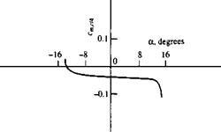
Finally, we turn our attention to the values of moment coefficients. Figure 1.48 illustrates the variation of cm<e/4 for the NACA 63-210 airfoil. Note that this is a negative quantity; all conventional airfoils produce negative, or “pitch-down,” moments. (Recall the sign convention for moments given in Section 1.5.) Also, notice that its value is on the order of —0.035. This value is typical of a moment coefficient—on the order of hundredths.
|
|
|
|

With this, we end our discussion of typical values of the aerodynamic coefficients defined in Section 1.5. At this stage, you should reread this section, now from the overall perspective provided by a first reading, and make certain to fix in your mind the typical values discussed—it will provide a useful “calibration” for our subsequent discussions.


