Background to Aerodynamically Balanced Control Surfaces
When airplanes and their control surfaces became large and airplane speeds rose to several hundred miles per hour, control forces grew to the point where even the Gough – Beard-McAvoy force limits were exceeded. Pilots needed assistance to move control surfaces to their full travels against the pressure of the air moving past the surfaces. An obvious expedient was to use those same pressures on extensions of the control surface forward of the hinges, to balance the pressure forces that tried to keep the control surfaces faired with the wing.
The actual developmental history of aerodynamically balanced control surfaces did not proceed in a logical manner. But a logical first step would have been to establish a background for design of the balances by developing design charts for the forces and hinge moments for unbalanced control surfaces. That step took place first in Great Britain (Glauert, 1927). Glauert’s calculations were based on thin airfoil theory. W. G. Perrin followed in the next year with the theoretical basis for control tab design (Perrin, 1928).
|
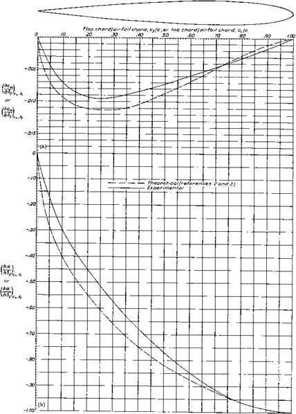
Figure 5.1 Pitching moment and control effectiveness parameters for plain flaps on the NACA 0009 airfoil, derived from pressure distributions. The dashed lines are Glauert’s thin airfoil theory. (From Ames and Sears, NACA Rept. 721, 1941) |
The next significant step in the background for forces and hinge moments for unbalanced control surfaces was NACA pressure distribution tests on a NACA 0009 airfoil, an airfoil particularly suited to tail surfaces (Ames, Street, and Sears, 1941). Figures 5.1 and 5.2 compare those results with Glauert’s theory. The trends with control surface hinge position along the airfoil chord match Glauert’s thin airfoil theory exactly, but with lower flap effectiveness and hinge moment than the theoretical values. Ames and his associates developed
|
Figure 5.2 Hinge moment parameters for plain flaps on the NACA 0009 airfoil, derived from pressure distributions. The dashed lines are Glauert’s thin airfoil theory. (From Ames and Sears, NACA Rept. 721, 1941) |
a fairly complex scheme to derive three-dimensional wing and tail surface data from the two-dimensional design charts. That NACA work was complemented for horizontal tails by a collection of actual horizontal tail data for 17 tail surfaces, 8 Russian and 3 each Polish, British, and U. S. (Silverstein and Katzoff, 1940). Full control surface design charts came later, with the publication of stability and control handbooks in several countries (see Chapter 6, Sec. 2.6).
5.2 Horn Balances
The first aerodynamic balances to have been used were horn balances, in which area ahead of the hinge line is used only at the control surface tips. In fact, rudder horn balances appear in photos of the Moisant and Bleriot XI monoplanes of the year 1910. It is doubtful that the Moisant and Bleriot horn balances were meant to reduce control forces on those tiny, slow airplanes. However, the rudder and aileron horn balances of the large Curtiss F-5L flying boat of 1918 almost certainly had that purpose.
Wind-tunnel measurements of the hinge moment reductions provided by horn balances show an interesting characteristic. Control surface hinge moments arise from two sources: control deflection with respect to the fixed surface (5) and angle of attack of the fixed or
|
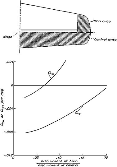
Figure 5.3 Typical hinge moment parameter variations with size for unshielded horn aerodynamic balances. The hinge moment due to angle of attack Cha is affected more strongly by the horn balance than by the hinge moment due to surface deflection Ch5. (From Phillips, NACA Rept. 927, 1948) |
main surface (a). The relationship is given in linearized dimensionless form by the equation Ch = ChsS + Chaa, where the hinge moment coefficient Ch is the hinge moment divided by the surface area and mean chord aft of the hinge line and by the dynamic pressure. Chs and Cha are derivatives of Ch with respect to 8 and a, respectively. Both derivatives are normally negative in sign. Negative Ch8 means that when deflected the control tends to return to the faired position. Negative Cha means that when the fixed surface takes a positive angle of attack the control floats upward, or trailing edge high.
Upfloating control surfaces reduce the stabilizing effect of the tail surfaces. It was discovered that horn balances produce positive changes in Cha, reducing the upfloating tendency and increasing stability with the pilot’s controls free and the control surfaces free to float (Figure 5.3). This horn balance advantage has to be weighed against two disadvantages. The aerodynamic balancing moments applied at control surface tips twist the control surface. Likewise, flutter balance weights placed at the tips of the horn, where they have a good moment arm with respect to the hinge line, lose effectiveness with control surface twist.
A horn balance variation is the shielded horn balance, in which the horn leading edge is set behind the fixed structure of a wing or tail surface. Shielded horn balances are thought to be less susceptible to accumulating leading-edge ice. Shielded horn balances are also thought to be less susceptible to snagging a pilot’s parachute lines during bailout.


