Blade Flapping Motions
Blade motions relative to the main rotor hub horizontal hinges in the forward flight regime are called flapping motions. These motions arise when the blade equilibrium relative to the horizontal hinges is disrupted because of azimuthal variation of the blade thrust.
When the blade thrust and moment increase it flaps upward, and when the thrust and moment decrease it flaps downward. Let us see how the blade flapping
angles vary with azimuth.
For the advancing blade with ip from 0 to 90° the resultant flow velocity over the blade and the blade thrust and moment increase, and the blade flaps upward — the flapping angle and the vertical velocity increase. At the 90° azimuth the upward vertical flapping velocity reaches the maximal value.
For ip > 90° the blade thrust and vertical flapping velocity decrease, while the flapping angle continues to increase.
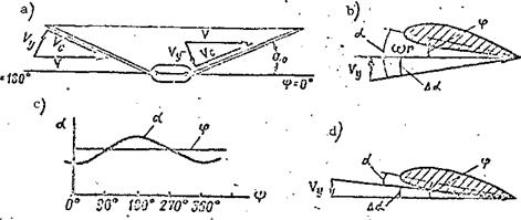
The blade flapping motions are affected not only by variation of the resultant velocity, hut also by variation of the blade element angle of attack caused by the main rotor coning angle. As a result of the coning angle the undisturbed stream approaches the blade located at the 180° azimuth at some angle from below, and approaches the blade located at the 360° azimuth at some angle from above (Figure 37a).
The undistrubed stream velocity vector can be broken down into the components: V perpendicular to the blade longitudinal axis, and Vg parallel to
the blade axis. The latter is called the slip velocity. The blade element
angle of attack and thrust are independent of V. At the 180° azimuth the
s
vector Vy is directed at the blade from below, consequently this leads to increase of the blade element angle of attack by the magnitude Да (Figure 37b).
The induced flow velocity is not shown in the figure.
At the 360° azimuth (Figure 37a) the vector is directed downward toward the blade, which leads to reduction of the blade element angle of attack (Figure 37d). Thus, as a result of coning the angle of attack of each blade element changes azimuthally from a maximum at the 180° azimuth to a minimum at the 360° azimuth. At the 90°and 270° azimuths, the angles of 1$A.
attack equal the incidence angle (without account for the induced velocity and the flapping motion velocity), Figure 37c.
|
Figure 37. Blade element angle of attack as a function of main rotor coning angle. |
But the increase of the blade element angle of attack as a result of the coning angle for ф > 90° leads to increase of the thrust and further upward flapping. As a result of this effect, the maximal blade flapping angle in the forward flight regime will occur at ф и 210°. In this case equilibrium of the blade relative to the horizontal hinge is established. As the blade motion continues around the circle, the blade thrust decreases as a result of reduction of the resultant velocity and the blade element angle of attack, and equilibrium is disrupted, i. e.,
MT<i MQ + MN.
The vertical downward flapping velocity will be maximal at the 270° azimuth. Equilibrium is reached again for ф 30° and the flapping angle will be minimal.
This variation of the flapping angle in azimuth is possible in the forward flight regime if the blade incidence angle does not change in azimuth and account is not taken of elastic twisting of the blade under the influence of the aerodynamic forces.


