Classical Thin Airfoil Theory: The Symmetric Airfoil
Some experimentally observed characteristics of airfoils and a philosophy for the theoretical prediction of these characteristics have been discussed in the preceding sections. Referring to our chapter road map in Figure 4.2, we have now completed the central branch. In this section, we move to the right-hand branch of Figure 4.2, namely a quantitative development of thin airfoil theory. The basic equations necessary for the calculation of airfoil lift and moments are established in this section, with an application to symmetric airfoils. The case of cambered airfoils will be treated in Section 4.8.
For the time being, we deal with thin airfoils; for such a case, the airfoil can be simulated by a vortex sheet placed along the camber line, as discussed in Section 4.4. Our purpose is to calculate the variation of у (s) such that the camber line becomes a streamline of the flow and such that the Kutta condition is satisfied at the trailing edge; that is, у (ТЕ) = 0 [see Equation (4.10)]. Once we have found the particular y(s) that satisfies these conditions, then the total circulation Г around the airfoil is found by integrating y(s) from the leading edge to the trailing edge. In turn, the lift is calculated from Г via the Kutta-Joukowski theorem.
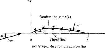
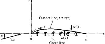
Consider a vortex sheet placed on the camber line of an airfoil, as sketched in Figure 4.17a. The freestream velocity is Voo, and the airfoil is at the angle of attack a. The x axis is oriented along the chord line, and the z axis is perpendicular to the chord. The distance measured along the camber line is denoted by 5. The shape of the camber line is given by z = z(x). The chord length is c. In Figure 4.17a, w’ is the component of velocity normal to the camber line induced by the vortex sheet; w’ = w'(s). For a thin airfoil, we rationalized in Section 4.4 that the distribution of a vortex sheet over the surface of the airfoil, when viewed from a distance, looks almost the same as a vortex sheet placed on the camber line. Let us stand back once again and view Figure 4.17a from a distance. If the airfoil is thin, the camber line is close to the
|
|
|
(b) Vortex sheet on the chord line Figure 4.1 7 Placement of the vortex sheet for thin airfoil analysis. |
chord line, and viewed from a distance, the vortex sheet appears to fall approximately on the chord line. Therefore, once again, let us reorient our thinking and place the vortex sheet on the chord line, as sketched in Figure 4.17b. Here, у = у (дг). We still wish the camber line to be a streamline of the flow, and у = y(x) is calculated to satisfy this condition as well as the Kutta condition y(c) = 0. That is, the strength of the vortex sheet on the chord line is determined such that the camber line (not the chord line) is a streamline.
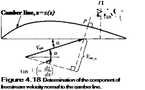
For the camber line to be a streamline, the component of velocity normal to the camber line must be zero at all points along the camber line. The velocity at any point in the flow is the sum of the uniform freestream velocity and the velocity induced by the vortex sheet. Let V^,, be the component of the freestream velocity normal to the camber line. Thus, for the camber line to be a streamline,
Voc. n + u/(.v) = 0 [4.12]
at every point along the camber line.
An expression for Vco. n in Equation (4.12) is obtained by the inspection of Figure 4.18. At any point P on the camber line, where the slope of the camber line is
|
|
|
|
 |
![]()
dz/dx, the geometry of Figure 4.18 yields

![]() [4.13]
[4.13]
For a thin airfoil at small angle of attack, both a and tan-1 (—dz/dx) are small values. Using the approximation that sin в ~ tan 0 яа 9 for small 9, where 9 is in radians, Equation (4.13) reduces to
![]() [4.14]
[4.14]
Equation (4.14) gives the expression for to be used in Equation (4.12). Keep in mind that, in Equation (4.14), a is in radians.
Returning to Equation (4.12), let us develop an expression for w'(s) in terms of the strength of the vortex sheet. Refer again to Figure 4.17b. Here, the vortex sheet is along the chord line, and w'(s) is the component of velocity normal to the camber line induced by the vortex sheet. Let w(x) denote the component of velocity normal to the chord line induced by the vortex sheet, as also shown in Figure 4.17Й. If the airfoil is thin, the camber line is close to the chord line, and it is consistent with thin airfoil theory to make the approximation that
![]() w'(s) ЯИ w(x)
w'(s) ЯИ w(x)
An expression for w(x) in terms of the strength of the vortex sheet is easily obtained from Equation (4.1), as follows. Consider Figure 4.19, which shows the vortex sheet along the chord line. We wish to calculate the value of w(x) at the location*. Consider an elemental vortex of strength у d% located at a distance f from the origin along the chord line, as shown in Figure 4.19. The strength of the vortex sheet у varies with
|
* w
£—0-^0—О – e—e4-e—0-
Figure 4.1 9 Calculation of the induced velocity at the chord line.
the distance along the chord; that is, у = у (£). The velocity dw at point x induced by the elemental vortex at point § is given by Equation (4.1) as
![]() Y<M)dS
Y<M)dS
2tz (x — I)
In turn, the velocity w(x) induced at point x by all the elemental vortices along the chord line is obtained by integrating Equation (4,16) from the leading edge (£ = 0) to the trailing edge (| = c):
Combined with the approximation stated by Equation (4.15), Equation (4.17) gives the expression for w'(s) to be used in Equation (4.12).
 |
|
Recall that Equation (4.12) is the boundary condition necessary for the camber line to be a streamline. Substituting Equations (4.14), (4.15), and (4.17) into (4.12), we obtain
the fundamental equation of thin airfoil theory, it is simply a statement that the camber line is a streamline of the flow.
Note that Equation (4.18) is written at a given point x on the chord line, and that dz/dx is evaluated at that point x. The variable § is simply a dummy variable of integration which varies from 0 to c along the chord line, as shown in Figure 4.19. The vortex strength у = у (|) is a variable along the chord line. For a given airfoil at a given angle of attack, both a and dz/dx are known values in Equation (4.18). Indeed, the only unknown in Equation (4.18) is the vortex strength y(£). Hence, Equation (4.18) is an integral equation, the solution of which yields the variation of у (I) such that the camber line is a streamline of the flow. The central problem of
thin airfoil theory is to solve Equation (4.18) for у (f), subject to the Kutta condition, namely, y(c) = 0.
In this section, we treat the case of a symmetric airfoil. As stated in Section 4.2, a symmetric airfoil has no camber; the camber line is coincident with the chord line. Hence, for this case, dz/dx = 0, and Equation (4.18) becomes
|
|
In essence, within the framework of thin airfoil theory, a symmetric airfoil is treated the same as a flat plate; note that our theoretical development does not account for the airfoil thickness distribution. Equation (4.19) is an exact expression for the inviscid, incompressible flow over a flat plate at angle of attack.
To help deal with the integral in Equations (4.18) and (4.19), let us transform f into 0 via the following transformation;
£ = ^(1 — cos 0) [4.20]
Since x is a fixed point in Equations (4.18) and (4.19), it corresponds to a particular value of 0, namely, 0q, such that
![]()
![]() [4.21]
[4.21]
Also, from Equation (4.20),
![]() – sin в dd 2
– sin в dd 2
Substituting Equations (4.20) to (4.22) into (4.19), and noting that the limits of integration become в = 0 at the leading edge (where £ = 0) and в = л at the trailing edge (where £ = c), we obtain
1 ![]() f71 y(e)sine dd
f71 y(e)sine dd
2л Jo cos в — cos e0
A rigorous solution of Equation (4.23) for у (в) can be obtained from the mathematical theory of integral equations, which is beyond the scope of this book. Instead, we simply state that the solution is
|
|
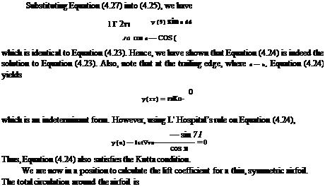
We can verify this solution by substituting Equation (4.24) into (4.23) yielding
 |
 cosпв dd
о cos в — cos во
|
Using Equation (4.26) in the right-hand side of Equation (4.25), we find that Eoo a f71 (1+cos 6)d6 V^a / f71 d0 f71 cos Odd Jo cos в – cos 90 7t Jo |
 |
|
|
|
|
|
 |
|
|
|
|
|
|
|
|
|
|
|
|
|
|
|
|
|
|
|
Substituting Equation (4.31) into (4.32), we have _ тгасрорУ^
1 і Pocked)
![]()
![]()
сі = 2ла
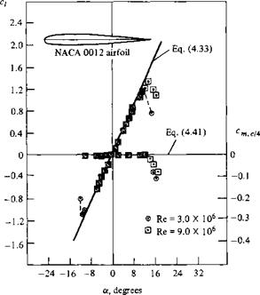
Equations (4.33) and (4.34) are important results; they state the theoretical result that the lift coefficient is linearly proportional to angle of attack, which is supported by the experimental results discussed in Section 4.3. They also state that the theoretical lift slope is equal to 2л rad-1, which is 0.11 degree-1. The experimental lift coefficient data for an NACA 0012 symmetric airfoil are given in Figure 4.20; note that Equation (4.33) accurately predicts с/ over a large range of angle of attack. (The NACA 0012 airfoil section is commonly used on airplane tails and helicopter blades.)
![]()
|
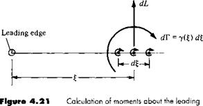
The moment about the leading edge can be calculated as follows. Consider the elemental vortex of strength у (£) located a distance £ from the leading edge, as sketched in Figure 4.21. The circulation associated with this elemental vortex is dF = y(%)d%. In turn, the increment of lift dl. contributed by the elemental vortex is dL = Poo Voc This increment of lift creates a moment about the leading edge dM = — £ (dL). The total moment about the leading edge (LE) (per unit span) due to the entire vortex sheet is therefore
 |
|
|
|
|
|
|
|
|
|
|
|
|
|
|
|
|
|
|
|
|
|
|
|
|

![]()
From Equation (1.22), the moment coefficient about the quarter-chord point is
![]() Cm, с/4 — Cm. le T ^
Cm, с/4 — Cm. le T ^
Combining Equations (4.39) and (4.40), we have
[4.41]
In Section 1.6, a definition is given for the center of pressure as that point about which the moments are zero. Clearly, Equation (4.41) demonstrates the theoretical result that the center of pressure is at the quarter-chord point for a symmetric airfoil.
By the definition given in Section 4.3, that point on an airfoil where moments are independent of angle of attack is called the aerodynamic center. From Equation (4.41), the moment about the quarter chord is zero for all values of a. Hence, for a symmetric airfoil, we have the theoretical result that the quarter-chord point is both the center of pressure and the aerodynamic center.
The above theoretical result for cm>c/4 = 0 is supported by the experimental data given in Figure 4.20. Also, note that the experimental value of cmc/4 is constant over a wide range of a, thus demonstrating that the real aerodynamic center is essentially at the quarter chord.
Let us summarize the above results. The essence of thin airfoil theory is to find a distribution of vortex sheet strength along the chord line that will make the camber line a streamline of the flow while satisfying the Kutta condition у (ТЕ) = 0. Such a vortex distribution is obtained by solving Equation (4.18) for y(%), or in terms of the transformed independent variable в, solving Equation (4.23) for у (в) [recall that Equation (4.23) is written for a symmetric airfoil]. The resulting vortex distribution у (в) for a symmetric airfoil is given by Equation (4.24). In turn, this vortex distribution, when inserted into the Kutta-Joukowski theorem, gives the following important theoretical results for a symmetric airfoil:
1. сі = 2л a.
2. Lift slope = 27Г.
3. The center of pressure and the aerodynamic center are both located at the quarter-
chord point.


