Combination of a Uniform Flow with a Source and Sink
Consider a polar coordinate system with a source of strength Л located at the origin. Superimpose on this flow a uniform stream with velocity Vx moving from left to right, as sketched in Figure 3.22. The stream function for the resulting flow is the sum of Equations (3.57) and (3.72):
i/r = Loor sin в H—- 0 [3.74]
2тт
Since both Equations (3.57) and (3.72) are solutions of Laplace’s equation, we know that Equation (3.74) also satisfies Laplace’s equation; that is, Equation (3.74) describes a viable irrotational, incompressible flow. The streamlines of the combined flow are obtained from Equation (3.74) as
jf = Vxr sin0 H—– в = const [3.75]
2jt
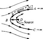
The resulting streamline shapes from Equation (3.75) are sketched at the right of Figure 3.22. The source is located at point D. The velocity field is obtained by
|
|||
|
|||
|
|
||
|
|||
![]()
Figure 3.22 Superposition of a uniform flow and a source; flow over a semi-infinite body.
differentiating Equation (3.75):
![]()
![]() 1 дф
1 дф
Vr =——– = Voo cos в +
r dO
Note from Section 3.10 that the radial velocity from a source is А/2л r, and from Section 3.9 the component of the freestream velocity in the radial direction is Voo cos в. Hence, Equation (3.76) is simply the direct sum of the two velocity fields—a result which is consistent with the linear nature of Laplace’s equation. Therefore, not only can we add the values of ф or r/r to obtain more complex solutions, we can add their derivatives, that is, the velocities, as well.
The stagnation points in the flow can be obtained by setting Equations (3.76) and
(3.77)
equal to zero:
Solving for r and в, we find that one stagnation point exists, located at (г, в) = (A/2jrV00, tt), which is labeled as point В in Figure 3.22. That is, the stagnation point is a distance (A/2jrV0O) directly upstream of the source. From this result, the distance DB clearly grows smaller if is increased and larger if A is increased— trends that also make sense based on intuition. For example, looking at Figure 3.22, you would expect that as the source strength is increased, keeping the same, the stagnation point В will be blown further upstream. Conversely, if V-y_ is increased, keeping the source strength the same, the stagnation point will be blown further downstream.
If the coordinates of the stagnation point at В are substituted into Equation (3.75), we obtain
|

|
|
Hence, the streamline that goes through the stagnation point is described by ijr = A/2. This streamline is shown as curve ABC in Figure 3.22.
Examining Figure 3.22, we now come to an important conclusion. Since we are dealing with inviscid flow, where the velocity at the surface of a solid body is tangent to the body, then any streamline of the combined flow at the right of Figure 3.22 could be replaced by a solid surface of the same shape. In particular, consider the streamline ABC. Because it contains the stagnation point at B, the streamline ABC is a dividing streamline; that is, it separates the fluid coming from the freestream and the fluid emanating from the source. All the fluid outside ABC is from the freestream, and all the fluid inside ABC is from the source. Therefore, as far as the freestream is concerned, the entire region inside ABC could be replaced with a solid body of the same shape, and the external flow, that is, the flow from the freestream, would not feel the difference. The streamline xfr — A/2 extends downstream to infinity, forming a semi-infinite body. Therefore, we are led to the following important interpretation. If we want to construct the flow over a solid semi-infinite body described by the curve ABC as shown in Figure 3.22, then all we need to do is take a uniform stream with velocity Voc and add to it a source of strength Л at point D. The resulting superposition will then represent the flow over the prescribed solid semi-infinite body of shape ABC. This illustrates the practicality of adding elementary flows to obtain a more complex flow over a body of interest.
The superposition illustrated in Figure 3.22 results in the flow over the semiinfinite body ABC. This is a half-body that stretches to infinity in the downstream direction (i. e., the body is not closed). However, if we take a sink of equal strength as the source and add it to the flow downstream of point D, then the resulting body shape will be closed. Let us examine this flow in more detail.
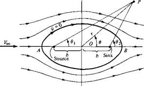
Consider a polar coordinate system with a source and sink placed a distance b to the left and right of the origin, respectively, as sketched in Figure 3.23. The strengths of the source and sink are A and —A, respectively (equal and opposite). In addition, superimpose a uniform stream with velocity Ex,, as shown in Figure 3.23. The stream function for the combined flow at any point P with coordinates (г. 0) is obtained from Equations (3.57) and (3.72):
A A
if = ExT Sin0 + —01 – —02 2л 2л
or if = Vxr sin 0 + — (01 – 02) [3.80]
2л
The velocity field is obtained by differentiating Equation (3.80) according to Equations (2.151a and b). Note from the geometry of Figure 3.23 that 0] and 02 in Equation (3.80) are functions of r, 0, and b. In turn, by setting V = 0, two stagnation points are found, namely, points A and В in Figure 3.23. These stagnation points are located
|
Figure 3.23 Superposition of a uniform flow and a source-sink pair; flow over a Rankine oval. |
such that (see Problem 3.13)
J.b
О A — OB = b2 [3.81]
V ^Voo
The equation of the streamlines is given by Equation (3.80) as
Л r,
ф = V^r sin 0 H——- (0i — 02) = const [3.82]
2ix
The equation of the specific streamline going through the stagnation points is obtained from Equation (3.82) by noting that 0 = 0; = 02 = 7Г at point A and 0 = 0i = 02 = 0 at point B. Hence, for the stagnation streamline, Equation (3.82) yields a value of zero for the constant. Thus, the stagnation streamline is given by = 0, that is,
Л r,
Voor sin0 H——- (0i — 02) = 0 [3.83]
2tt
the equation of an oval, as sketched in Figure 3.23. Equation (3.83) is also the dividing streamline; all the flow from the source is consumed by the sink and is contained entirely inside the oval, whereas the flow outside the oval has originated with the uniform stream only. Therefore, in Figure 3.23, the region inside the oval can be replaced by a solid body with the shape given by т/r = 0, and the region outside the oval can be interpreted as the inviscid, potential (irrotational), incompressible flow over the solid body. This problem was first solved in the nineteenth century by the famous Scottish engineer W. J. M. Rankine; hence, the shape given by Equation (3.83) and sketched in Figure 3.23 is called a Rankine oval.


