CONFIGURATION VARIABLES
Changes in the lifting characteristics of delta type wings due to changes of geometry from the simple shapes considered in the previous section can only be determined by test. Considerable test data is available so that these effects including changes in planform shape, leading-edge radius, camber and control devices can be found and compared with the lift characteristics of the simple wing found by the modified theory.
Aspect Ratio. The effect of changes in aspect ratio sharp-edge delta wings based on low speed wing tunnel tests is given on figure 13. Since the potential flow lift term can only be estimated by determining the slope at CL= 0 and in accordance with equation 1 it varies as sin of cos2 oc, comparison with the calculated values are made based on the total lift. The agreement between the calculated total lift based on equations 1 and 3 and test data is good for the entire range to A = 2.3, and for angles of attack below where vortex bursting might be expected. The increase of the slope of the lift curve with aspect ratio and angle of attack predicted by the modified theory (5,a) and test data is thus confirmed.
|
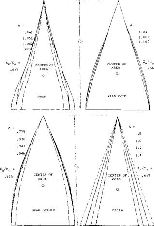
Figure 14. Planform shapes of slender delta wing tested, including ogee, gothic and delta types. |
.030r
.025- .020-
Л" .015-
OB 09 10 ~U І2 В І4
Figure 15. Potential flow lift of ogee, gothic and delta wings collapsed to a single line.
Planform Shape. The effects of changes of planform shape from the simple delta wing on the potential flow and vortex lift coefficients has been found for a series of sharp leading-edge delta type wings for A from.75 to 1.25 (6). The shapes evaluated include ogee, gothic and delta wings, figure 14. The test data for these wings were collapsed into a single line (7) for both the potential flow and vortex lift components.
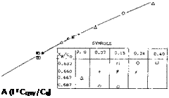
Potential Flow Lift. A single line for the potential flow lift curve slope of the series of wings was obtained, figure 15, plotting dC /do as a function of the factor A(1 + C99 /C0). By modifying the aspect ratio by the above factor the planform shape effects are normalized more in line with theory. Since the potential flow lift curve slope can only be estimated from test data at zero CL the data given on figure 15 applies strictly for low angles of attack. To find the slope due to changes in angle of attack the data should be modified by the factor sin or cos2a. The corresponding theoretical line for the potential flow lift calculated from equation 1 and figure 9 is also shown on figure 15. This curve indicates a loss of lift in comparison to the theoretical which increases with aspect ratio.
(7) Delta wings experimental characteristics:
a) Fink, Zeit Flug Wissenschaft 1956 p 247.
b) British ARC, RM 2518 & 3077.
c) NACA, Tech Note 1650.
d) Hall, Wing-Body Configurations, NACA RM A53A30.
e) See also (6).
f) McKay, Reversing Triangular Wing Body, NACA 51H23.
g) Lange, 0012 Wings, ‘ZWB Rpt UM 1023/5; NACA TM 1176.
![]() Vortex Lift. The vortex lift element of delta type
Vortex Lift. The vortex lift element of delta type
slender wings can be correlated into a single line, as shown on figure 16, by modifying the normal force slope using a factor which depends on the span at a semispan from the trailing-edge. This factor
f(S) = bVb
 where b’ = the span at a distance b/2 from the trailing edge. For the range of aspect ratios considered good correlation is obtained when the corrected slope is plotted as a function of o(c /А, figure 16. At /А above 20 the correlated data is below that calculated by theory equation 3, figure 10, indicating the vortices have started to break down in lift effectiveness.
|
>*> |
|
|
|
|
|
|
|
|
|
|
|
|
|
|
|
|
|
|
|
|
![]()
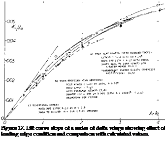
Leading-Edge Shape. The leading-edge shape, which can also be considered to be the tip shape of delta wings, has a large effect on the lift produced by the wings. It appears that the proper formation of the vortex in conjunction with the spanwise flow is essential to the production of lift. As previously noted, the formation of the vortex and estimation of its lift is based on the assumption of sharp edges as illustrated in figure 8. Any deviation in shape from the assumed sharp edge can be expected to produce a reduction in the lift. From the flow patterns observed (8) it appears that the effect of leading-edge shape mainly effects the vortex lift. This is difficult to confirm as the vortex and circulation lift components are not measured separately.
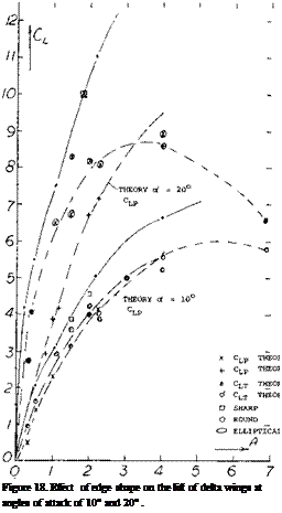
Vortex Lift – Leading-Edge Shape. Because of the non-linear shape of the lift curve of delta wings, C L is examined at two different angles of attack, 10 and 20 degrees, as a function of aspect ratio, figure 18. The test data is divided up into that for sharp or round leading wings and is compared with the lift calculated by equations 1 and 3. The available data on sharp leading – edge wings shows good agreement with the calculated values at both angles. The wings with round leading edges have a marked reduction in lift with increasing aspect ratio. This is especially true at the higher angles and aspect ratios above 2.0 where the lift drops off with increasing A. For instance at A above four the lift curve slope begins to decrease when taken at oi = 10 , figure 18. This is
due to vortex breakdown as discussed in the next section.
dihedral angle plus an angle at the leading edge of 17 degrees appears to be the most effective way of improving lift.
 <L
<L
|
|
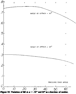
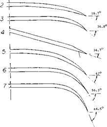
Camber. To obtain the desired characteristics of delta wings at the high speed flight condition camber may be used, (9,a, b). In this case camber was used to obtain design lift coefficients as high as.075 with the achieved value being 85 to over 100% of the design value. The lift characteristic of the wing with camber appears to follow the uncamber wing with an increment equal to the design value. For wings with an ogee planform the use of camber increased the lift drag ratio (9,b) and has a large influence on the position of center of pressure, depending on the chordwise distribution.
In (9,c) a series of wings of varying camber with an aspect ratio equal to 1.0 were tested to determine the non-linear effects, figure 19. The CL at of = 0, 10° and
20° show that the local angle at the leading edge has a large effect, especially over 40 degrees. The inverse
(8) Characteristics of sharp-edged arrowhead wings:
a) Buell, Flat-top Configuration, NASA Memo 3-S-59A.
b) Treon, Hypersonic Configuration, NASA TM X-364
c) Bartlett, Edge Shape, J Aeron Sci 19-55 p. 517.
d) Shanks, Six Plates, NASA TN D-1822 (1963).
e) Jorgensen, Cones with Plates, NACA Rpt 1378
![]()
 RUSSIAN TU-144
UNITED STATES SST
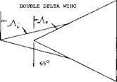
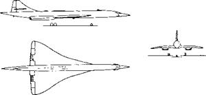
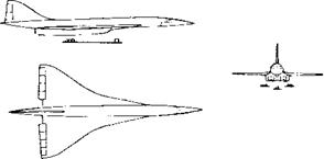
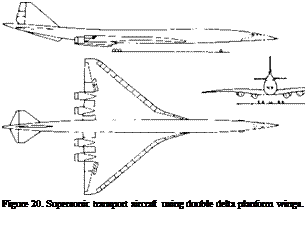
Double Delta Wings. The double delta wing is used for high speed airplanes for reducing the large rearward aerodynamic-center shift that occurs between subsonic to supersonic flight. Examples of double delta wing configurations are shown on figure 20 for supersonic transport type airplanes (10,d). This shift is obtained because of the change in aerodynamic loading from the rear delta at high speeds. Even with the use of the double delta configuration it may be necessary to shift fuel longitudinally to maintain the desired stability.
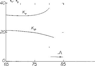
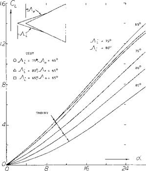
The effect of the use of a double delta wing planform on lift characteristics can be determined based on the leading-edge suction analogy (5,c). For the case where a glove or second delta is added to the basic wing the factors in the lift equation Kp and Kv are given as a function of the sweep angle of the leading edge, figure 21. For this case the vortex lift will increase with an increase of the first wing delta angle while the potential flow lift decreases. This is probably due to the increase in length of the leading-edge vortex and the effective decrease in aspect ratio due to the leading delta. The net result of this is a decrease of total lift compared to the basic wing, figure 22.
 |
The experimental data (10,e) given on figure 22 shows that nearly the same lift is obtained with the double delta wings as the basic wing. Although the level is below the theoretical values, the improvement is probably due to the delay of the vortex lift breakdown to higher angles. Thus, the addition of the glove does not appear to reduce the wing lift. The choice of the combination of double delta wings will thus depend on the center of pressure shift needed in the design and the lift drag ratio, see figure 31.
|
|
|
Figure 21. Potential flow and vortex lift factors, Kp and К v for 65 ° basic delta wing with glove. |
Wing + Bodies. As shown in Chapter XIX on the lift characteristics of streamline bodies, vortices are formed that are similar in nature to those produced with delta wings. These vortices lead to the 2 ex’ flow on the body and in the vicinity of the wing root with the result that a strong interaction is encountered. Thus, in determining the characteristics of the wing and fuselage it is necessary to consider:
a) effect of the wing vortices on the wing
b) interference of the wing vortices on the fuselage
c) effect of the fuselage vortices on the fuselage
d) interference of the fuselage vortices on the wing.
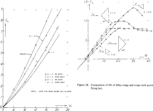
The influence of the fuselage on the lift curve slope of delta wings is given on figure 23 for A = 1 and 2. The 2 of cross flow of the body reduces the lift on the wing body combination. This is further confirmed by the two dimensional data of (11 ,b) which shows the effect of wing position. As the wing moves forward the lift increases as shown approaching the theoretical value for the wing alone. This would be expected as the body vortices influence a smaller portion of the wing as it moves forward. In (11) a theoretical procedure for calculating the lift of the combination is given which includes consideration of the fuselage vortices and gives good agreement with the experimental data. In this theory the wing is replaced by a continuous vortex distribution. The trailing vortices are then located in sheets inclined at an angle of Ofoo with respect to the wing plane. Non-linear lifting surface theory is then used to solve for the effects of these vortices on the wing (1 l, a).
|
Figure 22. Lift coefficient for wings with and without double delta planforms. |
![]()
(10) Double Delta wings:
a) Freeman, Low Speed Flight and Force Investigations NASA TN-4179.
b) Hopkins, Cranked Leading-edge Wing-Body Combinations M = .4 to 2.94, NASA TN D-4211.
c)  Corsiglia, Aircraft Model Double-Delta Wing Longitudinal and Lateral Characteristics, NASA TN-5102.
d) Boeing Document 1971.
e) Wentz, Sharp-edged Slender Wings, AIAA Paper 69-778.
![]()
![]()
![]()
![]() least as important in the aspect ratios tested for producing lift as the leading edge. It should be noted, however, that the simple conclusion as in (8,d), whereby a wing with zero trailing-edge span may be expected not to produce any circulation, does not appear to be correct. Regarding the second non-linear component of lift, the point-last delta shape is again seen to be the least effective. This result seems to be a confirmation of the end-plate principle presented above. In the shape considered, the lateral vortex sheets are canted in a direction reducing their effectiveness.
least as important in the aspect ratios tested for producing lift as the leading edge. It should be noted, however, that the simple conclusion as in (8,d), whereby a wing with zero trailing-edge span may be expected not to produce any circulation, does not appear to be correct. Regarding the second non-linear component of lift, the point-last delta shape is again seen to be the least effective. This result seems to be a confirmation of the end-plate principle presented above. In the shape considered, the lateral vortex sheets are canted in a direction reducing their effectiveness.
|
Delta – Point Flying Last. Delta wings are usually thought of and designed as flying with their vortex point first. Results of such a shape tested in the point-last direction are presented in figure 24. It is very interesting to see that the point-last plate has the smallest linear lift-curve slope, although it presents a “perfect:” leading edge to the stream. In other words, the trailing edge is at
(12) Vortex breakdown on delta wings:
a) Wentz, Vortex Breakdown on Sharp-edge Wings, AIAA Paper No. 69-778 and NASA CR-714.
b) Earnshaw, Vortex-breakdown Position-Sharp-edge, ARC, C. P. No. 828.
c) Lambourne, Breakdown of Certain Types of Vortex, NPC Report 1165.
d) Polhamus, Vortex-lift by L. E. Suction Analogy, J of Aircraft, April 1971.
e) Snyder, Theory of the Delta Wing, Wichita State U., AR66-4.
f) Lawford, Sharp-edge Delta Wing-Position L. E. Vortex Breakdown, RM 3338.


