Discrete Vortex Method
The discrete vortex method, which is presented here for solving the thin lifting airfoil problem, is based on the lumped-vortex element and serves for solving numerically the integral equation (Eq. ((5.39)) presented in Chapter 5. The advantage of the numerical approach is that the boundary conditions can be specified on the airfoil’s camber surface without a need for small-disturbance approximation. Also, two-dimensional interactions such as ground effect or multielement airfoils can be studied with great ease.
This method was introduced as an example in Section 9.8 and therefore its principles will be discussed here only briefly. To establish the procedure for the numerical solution, the six steps presented in Section 9.7 are followed:
Choice of singularity element. For this discrete-vortex method the lumped – vortex element is selected and its influence is given by Eq. (9.31) (or Eqs.
(10.9)
 |
||
and (10.10)):
Thus, the velocity at an arbitrary point (x, z) due to a vortex element of circulation Г; located at (xy, z,) is given by Eq. (11.1). This can be included in a subroutine, which will be called VOR2D:
(и, w) = VOR2D (Г;, x, z, Xj, z,) (11.2)
Such a subroutine is included in Program No. 13 in Appendix D.
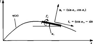
Discretization and grid generation. At this phase the thin-airfoil camberline (Fig. 11.2) is divided into N subpanels, which may be equal in length. The N vortex points (xj, Zj) will be placed at the quarter-chord point of each planar panel (Fig. 11.2). The zero normal flow boundary condition can be fulfilled on the camberline at the three-quarter chord point of each panel. These N collocation points (xh z,) and the corresponding N normal vectors n, along with the vortex points can be computed numerically or supplied as an input file. The vectors normal to the surface n, pointing outward at each of these points is found from the surface shape rj(x), as shown in Fig. 11.3:
![]()

 (11.3)
where the angle a, is defined as shown in Fig. 11.3. Similarly the tangential vector t, is
t, = (cos ah – sin or,) (11.3a)
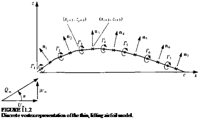
Since the lumped-vortex element chooses the correct circulation (Kutta condition), the last panel will inherently fulfill this requirement, and no additional specification of this condition is needed.
|
FIGURE 11J Nomenclature used in defining the geometry of a point singularity based surface panel. |
Influence coefficients. The normal velocity component at each point on the camberline is a combination of the self-induced velocity and the free-stream velocity. Therefore, the zero normal flow boundary condition can be presented
as
q • n = 0 on solid surface
Division of the velocity vector into the self-induced and free-stream components yields
(и, w) • n + (£/„, Же) • n = 0 on solid surface (11.4)
where the first term is the velocity induced by the singularity distribution on itself (hence “self-induced part”) and the second term is the free-stream component Q„e = (t/„, WJ), as shown in Fig. 11.2.
The self-induced part can be represented by a combination of influence coefficients, while the free-stream contribution is known and will be transferred to the right-hand side (RHS) of the boundary condition. To establish the self-induced portion of the normal velocity, at each collocation point, consider the velocity induced by the jth element at the first collocation point (in order to get the influence due to a unit strength Г; assume Г, = 1 in Eq. (11.2)):
(u, hOj, = VOR2D (Гу = 1, xu zu Xj, Zj) (11.2a)
The influence coefficient a, у is defined as the velocity component normal to the surface. Consequently, the contribution of a unit strength singularity element at collocation point 1 is
«1/ = (u, w)y • Пі (11.5)
The induced normal velocity component qnl, at point 1, due to all the elements is therefore
Чп = ЯцГі + Д12Г2 + Я13Г3 + • • • + йілгГ^
Note that the strength Г; is unknown at this point.
Fulfillment of the boundary condition on the surface requires that at each collocation point the normal velocity component will vanish. Specification of this condition (as in Eq. 11.4) for the first collocation point yields
ЯцГі + Q 12^*2 + Я13Г3 + • • • + aiNTN + (U„, Ж») • nj = 0
But, as mentioned earlier, the last term (free-stream component) is known and can be transferred to the right-hand side of the equation. Consequently, the right-hand side is defined as
RHS, = Ж») • n, (11.6)
Specifying the boundary condition for each of the N collocation points results in the following set of algebraic equations:
|
‘ «11 |
a12 |
«ш |
/г Д |
RHS |
|
Я21 |
Я22 |
a2N I |
RHS |
|
|
«31 |
a32 |
a3N I |
RHS |
|
|
flvi |
Я N2 ‘ • • |
aNNj |
r„l |
RHS |
This influence coefficient calculation procedure can be accomplished by using two “DO loops” where the outer loop scans the collocation points and the inner scans the vortices:
DO 1 і = 1, N collocation point loop
DO 1 j = 1, N vortex point loop
(u, w)0 = VOR2D (Г = 1.0, Xi, Zj, xjt z,)
^1) (^’ W)ij ‘
1 CONTINUE C END DO LOOP
Establish RHS vector. The right-hand side vector, which is the normal component of the free stream, can be computed within the outer loop of the previously described “DO loops” by using Eq. (11.6):
RHS,, = -(£/„, Ж.) • n,
where (£/„, Ж»,) = QJcos a, sin a). Using the formulation of Eq. (11.3) for the normal vector, the RHS becomes:
RHS, = -£2»(cos a sin <xt + sin a cos a,) (11.6a)
Note that a is the free-stream angle of attack (Fig. 11.2) and cr, is the ith panel inclination.
Solve linear set of equations. The results of the previous computations can be
T r2 Г, Г4 r5
>C ■ i0 10 1C
 ~4 Ac K
FIGURE 11.4
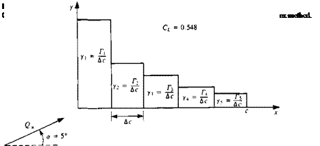
Representation of a lifting flat plate by five discrete vortices.
summarized (for each collocation point i) as
 |
|||
 |
|||
and as an example for the case of a flat plate (shown in Fig. 11.4) where only five equal-length elements (Ac = c/5) were used Eq. (11.7) becomes
This linear set of algebraic equations is diagonally dominant and can be solved by standard matrix methods, and the solution of the above set of algebraic equations is
|
ГД |
2.46092 |
|
1.09374 |
|
|
Г3 1 = яДс<2» sin a |
0.70314 |
|
w |
0.46876 |
|
Г si |
,0.27344 |
This solution is shown schematically in Fig. 11.5
Secondary computations: pressures, loads, velocities, etc. The resulting pressures and loads can be computed by using the Kutta-Joukowski theorem for
each panel j. Thus the lift and pressure difference are
![]()
ALj = pQSj
where Ac is the panel length. The total lift and moment per unit span (about the leading edge) are obtained by summing the contribution of each element:
l = 2al, (ИЮ)
7 = 1 N
M0 = 2 ALj(Xj cos a) (11.11)
y=i
while the nondimensional coefficients become
The following examples are presented to demonstrate possible applications of this method.
Example 1 Thin airfoil with parabolic camber. Consider the thin airfoil with parabolic camber of Section 5.4, where the camberline shape is
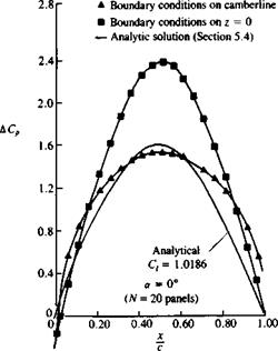
For small values of є <0.05 the numerical results are close to the analytic results, as shown in Fig. 11.6. However, when increasing the airfoil height e to 0.1, the effects of the small-disturbance approximation to the boundary conditions become more evident (see Fig. 11.7). Note that for the numerical solution the vortices were placed on the camberline where the boundary condition was satisfied, whereas for the analytical solution the vortex distribution and boundary conditions were specified on the x axis.
The effect of angle of attack is shown in Fig. 11.8 where a fairly large angle
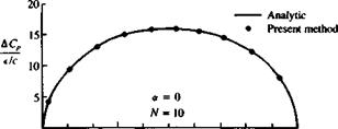 |
FIGURE 11.7
Effect of small-disturbance boundary condition on the computed pressure difference of a thin parabolic camber airfoil (a = 0).
 |
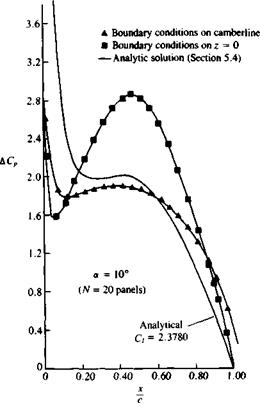 |
(ar = 10°) is used. Note the large suction peak at the leading edge, which is exaggerated by the analytic solution.
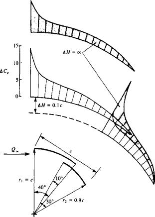
Example 2 Two-element airfoil. The advantage of this numerical solution technique is that it is not limited to the restrictions of small-disturbance boundary conditions. For example, a two-element airfoil with large deflection can be analyzed (and the results will have physical meaning when the actual flow is attached).
Figure 11.9 shows the geometry of the two-element airfoil made up of circular arcs and the pressure difference distributions. The interaction is shown by the plots of the close and separated elements (far from each other). When the elements are apart, the lift of the flrst element decreases and of the second increases.
Example 3 Sensitivity to grid. After this first set of numerical examples, some possible pitfalls of the numerical approach can be observed, and hopefully avoided later.
First note the method of paneling the gap region in the previous example of the two-element airfoil (Fig. 11.10). If very few elements are used, then it is
![]()
|
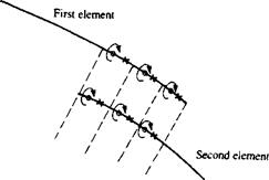 FIGURE 11.10
Method of paneling the gap region of a two-element airfoil (discrete vortex model).
|
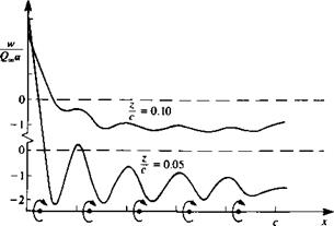
FIGURE 11.11 Schematic survey of induced normal velocity above a thin airfoil (as shown in Fig. 11.4) modeled by discrete vortices. |
always advised to align the vortex points with vortex points and collocation points with collocation points. We must remember that a numerical solution depends on the model and the grid (and hence is not unique). The convergence of a method can be tested by increasing the number of panels, which should result in a converging solution. Therefore, it is always advisable to use smaller panels than the typical length of the geometry that we are modeling. In the case of the two-element airfoil, the typical distance is the gap clearance, and (if possible with the more refined methods) panelling this area by elements of at least one-tenth the size of the gap is recommended.
Another important observation can be made by trying to calculate the velocity induced by the five-element, vortex representation of the flat plate of Fig. 11.4. If the velocity survey is performed at z = 0.05c, then the wavy lines shown in Fig. 11.11 are obtained. The waviness will disappear at larger distances, and in
|
|
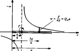
FIGURE 11.12
Downwash induced by a lumped-vortex element.
any computation careful investigation is needed for the near – and far-field effects of a particular singular element distribution.
Of course, in the previous examples, fairly accurate solutions were obtained with very few panels. This is because the lumped-vortex element induces the same downwash at the collocation point (3/4,0)a as the exact flat plate solution, as depicted by Fig. 11.12.


