Drawbacks of Main Rotor with Rigid Blade Retention
The main rotors of the early helicopters (TsAGIl-EA, for example) had blades which were rigidly attached to the hub. The blade incidence angle was changed by means of axial hinges. In their arrangement such rotors are similar to airplane variable pitch propellers. But the very first flights disclosed major deficiencies characteristic of these rotors.
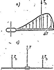
The thrust is created by all the blade elements, but the highest elemental forces will be those on the elements located at 3R/4 (see Figure 15d). The resultant of the elemental forces is applied at the blade center of pressure, which is located at the element with relative radius r = 0.7. This distribution of the elemental thrust forces and this positioning of the resultant leads to the creation of a large bending moment at the blade root (Figure 34a). The approximate magnitude of the blade root bending moment at the blade
attachment to the hub is determined from the formula M, , = T, 0.7R.
Dend b
Thus, if the rotor has four blades and the helicopter flight weight is 6000 kgf, the thrust of a single blade will be = 6000:4 = 1500 kgf. For main rotor diameter D = 20 m, М^еп^ = 1500 x 0.7 x 10 = 10,5000 kgf’m. This moment will be still larger for a heavy helicopter. The large bending moment creates a large load on the blade root. Moreover, the blade is subjected to a centrifugal force which reaches a magnitude of several tens of tons ; consequently the root portion of the blade operates under conditions of large loads. In order to avoid blade failure, the area of its root section must be increased, and this leads to increase of the structural weight and reduction of the helicopter’s useful load.
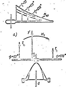
Since the blade thrust varies azimuthally, its bending moment also varies (Figure 34b). The variable bending causes fatigue stresses in the material of the structural elements, which can lead to rapid blade failure. The up and down bending vibrations of the blade tips reach high frequencies (up to 3-4 cycles per second), creating heavy vibration of the helicopter.
The blade thrust does not vary azimuthally in the vertical flight regime, and this means that the main rotor thrust vector, equal to the sum of the blade thrust forces T = T^k, lies along the hub axis (Figure 34c).
In the forward flight regime the blade thrust depends on the azimuth. /49
The thrust is maximal at the 90° azimuth and minimal at the 270° azimuth (Figure 34d). As a result of this variation, half the main rotor disk (advancing blades) has a higher thrust than the other half, formed by the retreating blades.
In this case the main rotor thrust vector T does not pass through the center of the hub, but rather at the distance a from the hub axis. The thrust moment ftL, = Та is created relative to the hub axis.

|
|
|

Since the hub axis is in the helicopter plane of symmetry, the main rotor thrust moment causes the entire helicopter to tend to overturn. This is termed the overturning moment. Thus the main rotor with rigid blade restraint has three major drawbacks:
presence of the overturning thrust moment in the forward flight regime; presence of large thrust bending moment at the blade root; variation of the blade thrust moment azimuthally.
All these drawbacks can be eliminated if the blades are attached to the hub by means of horizontal hinges.


