Evolution of the Equations of Motion
There is a reproduction in Chapter 1 of George H. Bryan’s equations of airplane motion on moving axes, equations developed from the classical works of Newton, Euler, and Lagrange. This astonishingly modern set of differential equations dates from 1911. Yet, Bryan’s equations were of no particular use to the airplane designers of his day, assuming they even knew about them.
This chapter traces the evolution of Bryan’s equations from academic curiosities to their present status as indispensable tools for the stability and control engineer. Airplane equations of motion (Figure 18.1) are used in dynamic stability analysis, in the design of stability augmenters (and automatic pilots), and as the heart of flight simulators.
18.1 Euler and Hamilton
One of the problems faced by Bryan in developing equations of airplane motion was the choice of coordinates to represent airplane angular attitude. Bryan chose the system of successive finite rotations developed by the eighteenth-century Swiss mathematician Leonhard Euler, with a minor difference. In Bryan’s words:
In the [Eulerian] system as specified in Routh’s Rigid Dynamics and elsewhere, the axes are first rotated about the axis of z, then about the axis of y, then again about the axis of z. The objection to this specification is that if the system receives a small rotation about the axis of x, this cannot be represented by small values of the angular coordinates.
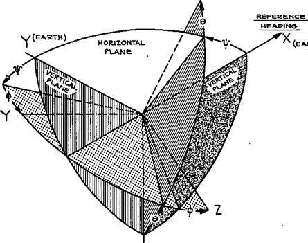
Bryan chose instead to rotate by a yaw angle Ф about the vertical axis, a pitch angle © about the lateral axis, followed by a roll angle Ф about the pitch axis – a sequence that has been followed in the field ever since. However, Bryan’s orthogonal body axes fixed in the airplane are rotated by 90 degrees about the X-axis as compared with modern practice. That is, the Y-axis is in the place of the modern Z-axis, while the Z-axis is the negative of the modern Y-axis (Figure 18.2).
Bryan’s Eulerian angles have served the stability and control community well in almost all cases. However, there were other choices that Bryan could have made that would have avoided a singularity inherent in Euler angles. The singularity shows up at pitch angles of plus or minus 90 degrees, the airplane pointing straight up or straight down. Then the equation for yaw angle rate becomes indeterminate.
The Euler angle singularity at 90 degrees is avoided by the use of either quaternions, invented by Sir W. R. Hamilton, or by direction cosines. The main disadvantage of quaternions and direction cosines as airplane attitude coordinates is their utter lack of intuitive feel. Flight dynamics time histories calculated with quaternions or direction cosines need to be translated into Euler angles for intelligent use. Except for simulation of airplane or space-vehicle vertical launch or of fighter airplanes that might dwell at these attitudes, the Euler angle singularity at 90 degrees is not a problem.
As the term implies, there are four quaternion coordinates; there are nine direction cosine coordinates. Since, as Euler pointed out, only three angular coordinates are required
to specify rigid-body attitudes, quaternion and direction cosine coordinates have some degree of redundancy. This redundancy is put to good use in modern digital computations to minimize roundoff errors in an orthogonality check. Another advantage to quaternion as compared with Euler angle coordinates is the simple form of the quaternion rate equations, which are integrated during flight simulation. Euler angle rate equations differ from each other, are nonlinear, and contain trigonometric functions. On the other hand, quaternion rate equations are all alike and are linear in the quaternion coordinates.
The nine direction cosine airplane attitude coordinates are identical to the elements of the 3-by-3 orthogonal matrix of transformation for the components of a vector between two
X
|
Z (EARTH) |
ORDER OF ROTATIONS
Y, © , Ф
Figure 18.2 The Euler angle sequence in most common use as airplane attitude coordinates in flight dynamics studies. This sequence was defined by B. Melvill Jones in Durand’s Aerodynamic Theory, in 1934. (From Abzug, Douglas Rept. ES 17935, 1955)
coordinate systems. As in the quaternion case, all nine direction cosine rate equations have the advantage of being alike in form, and all are also linear. The direction cosine rate equations are sometimes called Poisson’s equations. Airplane equations of motion using quaternions are common; those using direction cosine attitude coordinates are rare.
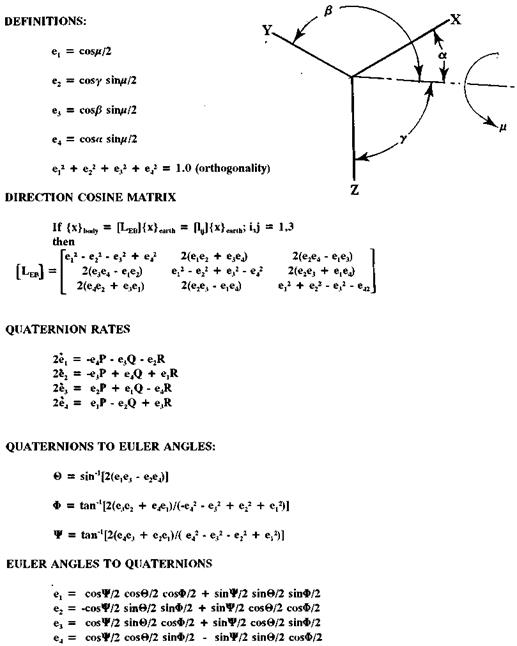
The Euler parameter form of quaternions uses direction cosines to define an axis of rotation with respect to axes fixed in inertial space. A rotation of airplane body axes about that axis brings body axes to their proper attitude at any instant (Figure 18.3). This goes back to one of Euler’s theorems, which states that a body can be brought to an arbitrary attitude by a single rotation about some axis. There is no intuitive feel for the actual attitude corresponding to a set of Euler parameters because the four parameters are themselves trigonometric functions of the direction cosines and the rotation angle about the axis.
The first published report bringing quaternions to the attention of airplane flight simulation engineers was by A. C. Robinson (1957). Robinson’s contribution was followed in 1960 by D. T. Greenwood, who showed the advantages of quaternions in error checking numerical computations during a simulation. A detailed historical survey of all three attitude coordinate systems is given by Phillips, Hailey, and Gebert (2001). The flight simulation
|
Figure 18.3 The Euler parameter form of quaternions used in some flight simulations to calculate airplane attitude. The upper group of equations defines the Euler parameters in terms of an axis of rotation of XYZ to a new attitude. {x}body are vector components on the rotated axes; {x} earth are the same components on the original axes. Transformations between Euler parameters and Euler angles are given in the lower two sets of equations. |
community appears to be divided on the choice between Euler angles and quaternions. In some cases, both are used in different flight simulators within a single organization. However, it is interesting that so many modern digital computations of airplane stability and control continue to use Euler angle coordinates in the 1911 Bryan manner.


