Fan-in-Wing Configuration
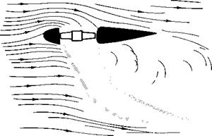
The fan-in-wing configuration consists of a fan submerged in the plane of a wing. The combined flow shown in Fig. 9-25 is sketched from a photograph taken from Ref. 13 of streak lines from water-tunnel data. The effect of the fan on the wing is somewhat similar to the section of a jet flap. The efflux from the fan is discharged in a direction normal to the plane of the wing and then turns in the downstream direction. In so doing a circulation is induced around the wing. We would expect, therefore, that the dimensionless coefficients of the fan-wing combination could be expressed as functions of the angle of attack and a “momentum coefficient ” of the fan.
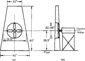
The semiwing and fan combination shown in Fig. 9-26 was tested in
|
Fig. 9-25. Flow through a fan-in-wing configuration. |
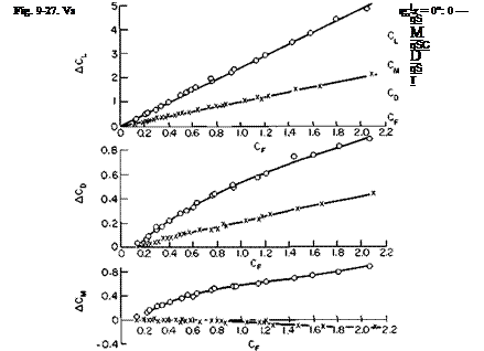
Ref. 14. The principal results are given in Fig. 9-27. In this figure, for example, ACL is the CL of the fan-wing combination minus CL for the wing without the fan rotating. The curves labeled “fan only” signify the forces on the fan when operating in the plane of the wing. By definition, ACL for the fan only is equal to CF. Notice that the induced lift on the wing is about 1.5
|
|
|
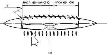
Fig. 9-26. Fan-in-wing configuration: (a) planform; (b) front view; (c) fan-in-wing configuration. |
times larger than the thrust of the fan; that is, the lift of the combination is 2.5 times the thrust of the fan. However, this ratio is not so great for the static case. According to the data of Ref. 14, the static thrust coefficient of the propeller above is 0.30, whereas CT of the combination is 0.5; CT is defined according to Eq. (4-57).
The static power coefficient, defined according to (4-57), is quoted in Ref. 14 as Cp = 0.59. The value seems rather high, yet it is in line with the
results of Ref. 13. In terms of the standard propeller coefficients, the figure of merit becomes
J3/2
ДрАР
or, in terms of CT and Cp,
 |
For this particular case, therefore, M = 0.475 for the combination.
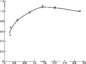
The effect of ground proximity on the static lift of the fan-wing combination is shown in Fig. 9-28. Below a height of approximately one fan diameter the static lift of the combination is seen to decrease significantly with decreasing height.
The configuration shown in Fig. 9-26 has both inlet and exit vanes for directing the flow entering and leaving the fan. The test results show that
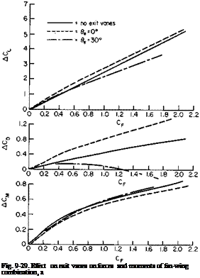
from the standpoint of lift and drag little is to be gained by using inlet vanes. In fact, for most of the angles and CF values tested the use of inlet vanes was detrimental to both the lift and the drag. The exit vanes, on the other hand, appear to offer some advantages. As shown in Fig. 9-29, the lift and pitching moment are only slightly affected by deflecting the exit vanes. The drag, however, is reduced appreciably at the high CF values by directing the fan efflux 20 or 30° rearward.
The effect of forward speed on the power required by the fan is shown in Fig. 9-30. Here the ratio of power required at a forward speed to the static
|
h/D Fig. 9-28. Effect on ground proximity on total static lift: h = distance above ground, D = fan diameter. |
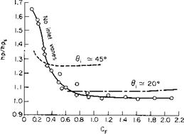
power required at the same fan rpm is plotted as a function of the propeller force coefficient. As can be seen, the power is relatively unaffected for values of CF above approximately 0.7. Below this value, however, the induced effects of the fan are not strong enough to prevent the flow from separating from the upstream lip of the duct; the result is a poor inflow to the fan. This power increase can be alleviated by deflecting the inlet vanes forward, as shown in the figure.
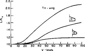
The lift augmentation provided to the wing by the fan in forward flight is not nearly so great as that for a tilt-wing aircraft where wing is submerged in the slipstream. For this reason the fan-in-wing configuration does not look promising as a STOL aircraft. This is shown quantitatively in Fig. 9-31 taken from Ref. 16 for three hypothetical aircraft, all with the same wing loading and wing area.
There is still no acceptable theory for predicting the performance of a fan-in-wing configuration. At best we will probably have to resort to a
|
Fig. 9-30. Ratio of power to static power for constant fan rpm. |
numerical solution such as that presented in Ref. 15. Here a lattice of horseshoe vortices replaces the wing-fan combination and the strength of the vortices is adjusted so that the induced velocities normal to the wing surface are zero and equal to a desired nonzero value at the fan location. Reference 17 follows the same procedure but includes a vortex tube that simulates the slipstream below the fan.
|
Fig. 9-31. Ratio of lift to static lift for fan-in-wing configurations compared with the tilt-wing. |
Problems
1. Given a straight tapered duct with an entrance diameter of 6 ft. a length of 8 ft. and an exit diameter of 4 ft. Calculate the velocity along the centerline at the mid-chord using the approximation of fig. 9—5 for a free-stream velocity of 100 fps. What is the value of Г?
2. A propeller is installed in the duct of problem one at mid-chord. If the thrust of the propeller is 1000 lbs., what is now the value of Г? What is the value of of the shroud thrust? What is the ideal HP required by the propulsor-shroud combination? For the same total thrust, what diameter of an open-propeller would give the same ideal power?
3. Design the rotor for problem 2 (pitch angle and chord) for a ten-bladed rotor having a constant section C/ of 0.5 and a tip speed of 600 fps.


